


4
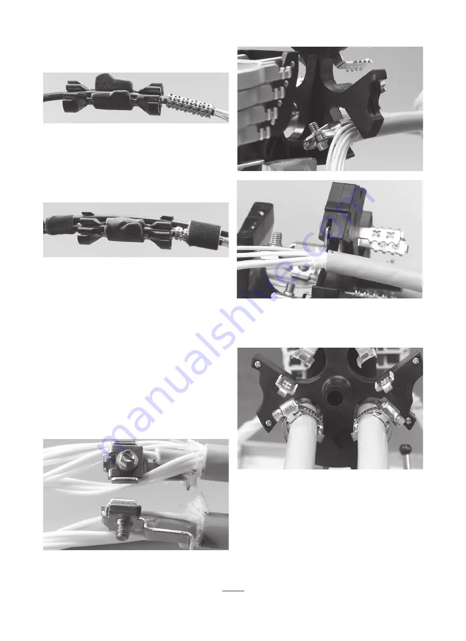
4.2.4 Mark the drop cable(s) 40 mm from the jacket. Align the metal
plate with the jacket and wrap it around the cable.
4.2.14 Insert the cable with the metal plate into the middle position of
the port splitter. Line up the end of the port splitter with the mark on the
cable.
Multi-out with the port splitter kit
Capacity:
maximum 3 cables
Cable range: from 3 – 6 mm
4.2.5 Flip the gel wings together and press to seal around the middle
cable.
4.2. 6 If required, insert other cable(s) on either side of the port
splitter. Keep gel wings in closed position during insertion of cable(s).
Note
: make sure gel wings are closed together after cable insertion.
4.2.7 Bundle the cables with vinyl tape on both sides of the port splitter.
Note: in case of central core (uni-tube) cable, remove the core at
150 mm leaving from the jacket.
4.3.1 Secure the strength member into the strength member
attachment.
4.3
Cable and strength member termination
Loose tube and central core
4.3.3 Insert strength member bracket into the slot in the frame. Top
picture shows main cable ports (1,2). Bottom picture shows the drop
cable ports (3,4).
4.3.4 Place the cable(s) between the cable retention brackets. Secure
the cable(s) with the supplied hose clamp(s)
Note
: the head of the hose clamp has to be positioned on top of the
cable retention bracket. Otherwise it might interfere with the base when
assembled.
4.3.2 Insert the cable assembly through the FOSC 450 closure base
and position it into the designated port.
Summary of Contents for FOSC-450A
Page 15: ...15 ...


