background image

5

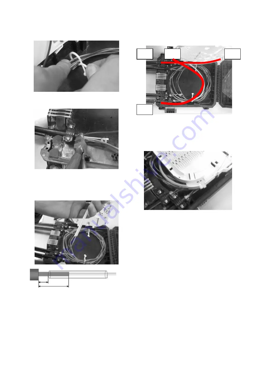
6.2  Secure the pass-through cable slack, as shown. 

6.3  Strip the input fiber cable 

6.4  Degrease the fiber bundle and slide the 

transportation tubes over the fibers with overlap 

50mm 

6.5  Route the transparent tubes to the tray entrance, as 

shown 

6.6  Secure the transportation tube at the tray entrance 

with two tie wraps.   

Note: Maximum two transportation tubes per tray 

entrance.  

Splicing and fiber storage 

7.1  Position the closure close to the splicing machine in a 

convenient location and secure the closure 

7.2  Slide the heat-shrinkable splice protection over one 

fiber and fuse fibers according to local 

recommendations and procedures. After the fusion 

splice is made, install the heat-shrinkable splice 

protection (e.g. SMOUV) with an appropriate heating 

source. Allow the splice protection to cool down to 

ambient temperature.   

# 1 

#4 

#4 

# 1 

100 mm 

50 mm 

Summary of Contents for FDC-W8-FAT

Page 1: ...1 2 Product description The FDC W8 FAT is a butt type gel sealed fiber optic splicing and patching closures designed for fiber access point applications in the telecom outside plant network FDC W8 FAT has 4 main cable ports and 8 drop cable ports Loop storage of 6m loose tubes allows 2 main cables loop through at the same time The closure accommodates up to 24 fusion splices or 8 mechanical splice...

Page 2: ...ion conditions precautions 3 1 The closures should be installed at temperature between 5 C and 45 C 3 2 Follow the installation instruction steps to ensure the performance of the closure 3 3 It is necessary to take precautions and keep the working space clean to protect the closure sealing materials and splices 4 Closures preparation 4 1 Open the closures by unscrew the all screws on the closure c...

Page 3: ...able clamp White snap block Blocking ring 8 9 3 Small Yes Yes 9 3 12 Small Remove Remove 12 14 Large Remove Remove Table 1 Cable clamp selection Clamp type White snap block 5 Cable Installation 5 1 Make a window cut of 1500mm and cut the strength member up to 50mm from the cable jacket end Note If the cable has jacket covered on strength member Please remove the jacket before installation 5 2 Clea...

Page 4: ...n 5 5 Screw tight the upper clamps Note After slightly tighten the first screw firmly tighten the second screw Then firmly tighten the first screw Note leave 10mm from the clamp end to the tip end for each cable as shown below 5 6 Secure cables with tie wraps as shown Cut the excess off 6 Fiber preparation 6 1 Loop the pass through cable slack as shown Note Use Port 1 Port 4 for one loop cable Use...

Page 5: ...te Maximum two transportation tubes per tray entrance 7 Splicing and fiber storage 7 1 Position the closure close to the splicing machine in a convenient location and secure the closure 7 2 Slide the heat shrinkable splice protection over one fiber and fuse fibers according to local recommendations and procedures After the fusion splice is made install the heat shrinkable splice protection e g SMO...

Page 6: ...as shown Do not deform the splice protector during insertion 7 4 Put on the tray lid 7 5 Put back the drop cable tray 7 6 Close the closure 8 Pole mount installation 8 1 Insert the two pole strips onto the closure as shown 8 2 Screw tight on the pole 9 Wall mount installation 9 1 Holes dimensions 219 mm 194mm ...

Page 7: ...he center screw and unlatch the top cover as shown 10 2 Fully open the cover as shown 10 3 For easy FIC insertion tilt the adapter as shown 10 4 Complete FIC connector assembly 10 5 Remove the dust cap and insert the FIC 10 6 Remove the drop cable dummy rods ...

Page 8: ...act your local CommScope representative for more information www commscope com FOSC SMOUV CommScope and all trademarks identified by or are registered trademarks or trademarks respectively of CommScope Inc 2018 CommScope Inc All Rights Reserved This product may be covered by one or more U S patents or their foreign equivalents For patents see www cs pat com For technical assistance customer servic...

Reviews: