background image

507713-01

Page 27 of 32

Issue 1623

High Altitude


This furnace is carefully designed for optimal performance under a wide range of operating conditions. To ensure proper operation at 

higher altitudes, certain adjustments and/or kits may be required.
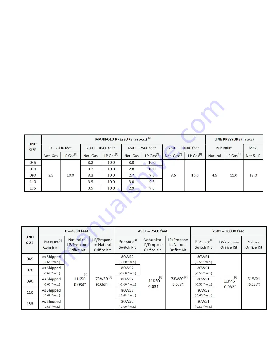
Manifold Pressure –


Between 2000 and 7500 ft, certain units require manifold pressure adjustments specified in Table 9. Manifold pressure should be 
measured, and adjusted as required during unit start up. Note: LP/Propane installations require a gas conversion Orifice Kit as specified 

in Table 10.

Pressure Switch –


Between 4501 and 7500 ft, some units may require a pressure switch change. Table 10 lists the available Pressure Switch Kits 
providing the minimum allowable pressure switch set points, in this altitude range, for each unit. The need for a Pressure Switch Kit 
may be evaluated by comparing the pressure measured at the pressure switch under steady state conditions (after 15 minutes of run 

time) against the as shipped switch set point. Insufficient negative pressure may lead to nuisance pressure switch trips and possible 

unit lock outs. 


Above 7500 feet, all units require both a burner orifice change and a pressure switch change per Table 10

1. Manifold pressure adjustments based on 1020 Btu/ft

3

 gas for natural and 2500 Btu/ft

3

 gas for LP (corrected to standard conditions). Consult local utility 

for actual local heating value.

2. A natural to LP/Propane gas conversion Orifice Kit is required to convert this unit. Refer to kit instructions for conversion procedure.
3. A high altitude natural Orifice Kit is required.

1. Minimum allowable set points for this altitude range. Application of a Pressure Switch with lower set point (less negative / closer to zero) is not 

permitted.

2. Kit contains burner orifices and gas valve regulator spring(s).

Table 9 - Manifold Pressure and Line Pressure at Various Altitudes

Table 10 - Orifice Kits and Pressure switch kits at various Altitudes

Summary of Contents for GUH80A

Page 1: ...or equivalent service agency or the gas supplier WARNING Manufactured By Comfort Aire Century 1900 Wellworth Ave Jackson MI 49203 This manual must be left with the homeowner for future reference INST...

Page 2: ...Return air from both sides 5 Bottom and one side return air 2 Flue outlet may be horizontal but furnace must be vented vertically 3 Optional external side return air filter kit cannot be used with th...

Page 3: ...a licensed professional installer or equivalent service agency or the gas supplier WARNING Certifications These units are CSA International certified to ANSI Z21 47 In the USA installation of gas fur...

Page 4: ...tions are met The vent system must be permanently installed per these installation instructions A room thermostat must control the furnace The use of fixed jumpers that will provide continuous heating...

Page 5: ...to the house for combustion negative pressure outside pressure is greater than inside pressure will build to the point that a downdraft can occur in the furnace vent pipe or chimney As a result combus...

Page 6: ...aining the furnace the return air must be handled by ducts which are sealed to the furnace casing and which terminate outside the space containing the furnace This is especially important when the fur...

Page 7: ...area of at least one square inch per 2 000 Btu 645 mm per 59 kW per hour of the total input rating of all equipment in the enclosure If the equipment room is located against an outside wall and the ai...

Page 8: ...asher have been removed the rigid leg will not touch the blower housing Setting Equipment WARNING Do not install the furnace on its front or its back Do not connect the return air ducts to the back of...

Page 9: ...ity See Figure 9 2 Single side return air with optional return airbase See Figure 10 3 Bottom return air 4 Return air from both sides 5 Bottom and one side return air Figure 9 Single Side Return Air w...

Page 10: ...rs or ceiling joists When straps are used to suspend the unit in this way support must be provided for both the ends The straps must not interfere with the plenum or exhaust piping installation Coolin...

Page 11: ...wn the vent pipe and into the room This reverse flow of the flue gas may result in incomplete combustion and the formation of carbon monoxide gas This toxic gas might then be distributed throughout th...

Page 12: ...from 9 to 5 to avoid interference with inducer motor Mounting Screws Location Figure 15 Figure 16 UPFLOW POSITION Top Vent Discharge The combustion air inducer may be rotated clockwise or counterclock...

Page 13: ...ng must be brought into the unit from the bottom in order to accommodate the flue pipe Cut combustion air inducer tubing from 9 to 8 to avoid interference with inducer motor Remove make up box assembl...

Page 14: ...s WARNING Use self drilling sheet metal screws or a mechanical fastener to firmly secure the vent pipe to the round collar of the flue transition If self drilling screws are used to attach the vent pi...

Page 15: ...ey Never connect a Category I appliance to a chimney that is servicing a solid fuel appliance If a fireplace chimney flue is used to vent this appliance the fireplace opening must be permanently seale...

Page 16: ...etween sections of single wall connector piping shall be fastened by screws or other approved means 13 When the vent connector used for Category I appliances must be located in or pass through a crawl...

Page 17: ...onfigureations with zero lateral lengths are assumed to have no elbows in the vent system For all other vent configurations the vent system is assumed to have two 90 elbows For each additional 90 elbo...

Page 18: ...Capacity Type B Double Wall Vents with Type B Double Wall Connectors Serving Two or More Category I Appliances Common Vent Capacity Type B Double Wall Vents with Type B Double Wall Connectors Serving...

Page 19: ...problem is found during any of the preceding tests the common venting system must be modified to correct the problem Resize the common venting system to the minimum vent pipe size determined by using...

Page 20: ...Configurations NOTE BLACK IRON PIPE ONLY TO BE ROUTED INSIDE OF CABINET Figure 27 NOTE BLACK IRON PIPE ONLY TO BE ROUTED INSIDE OF CABINET Figure 26 Table 6 Gas Pipe Capacity ft hr m hr Note Capacity...

Page 21: ...ice to protect the furnace s electronic controls Precautions will help to avoid control exposure to electrostatic discharge by putting the furnace the control and the technician at the same electrosta...

Page 22: ...on This terminal is energized in the heating mode when the combustion air inducer is operating Any humidifier rated up to one amp can be connected to this terminal with the neutral leg of the circuit...

Page 23: ...507713 01 Page 23 of 32 Issue 1623 Wiring Diagram Figure 32 045 3 135 5 110 5 110 4 110 3 090 4 090 3 070 3 070 2...

Page 24: ...l The control stores the last 5 fault codes in non volatile memorty The most recent fault code is flashed first the oldest fault code is flashed last There is a 2 second pause between codes When the p...

Page 25: ...exactly a fire or explosion may result causing property damage personal injury or death WARNING 6 Move switch on gas valve to OFF Do not force See Figure 35 7 Wait five minutes to clear out any gas If...

Page 26: ...accurate reading shut off all other gas appliances connected to meter Supply Pressure Measurement A threaded plug on the inlet side of the gas valve provides access to the supply pressure tap Remove t...

Page 27: ...red at the pressure switch under steady state conditions after 15 minutes of run time against the as shipped switch set point Insufficient negative pressure may lead to nuisance pressure switch trips...

Page 28: ...heat anticipator setting if adjustable according to the amp draw listed on the wiring diagram that is attached to the unit NOTE Do not secure the electrical conduit directly to the air ducts or struct...

Page 29: ...rrectly Verify proper operation after servicing WARNING At the beginning of each heating season a qualified technician should check the system as follows Blower Check the blower wheel for debris and c...

Page 30: ...ate All service must be performed by a licensed professional installer or equivalent service agency or gas supplier Heating Parts Flame sensor Heat exchanger assembly Gas manifold Combustion air induc...

Page 31: ...1 1535 1469 1363 1257 1158 Med High 1420 1410 1368 1314 1273 1183 1103 1002 Med 1171 1168 1150 1126 1084 1022 935 817 Low 973 978 957 927 908 840 784 680 090B4 1 2 4 spd 10 x 10 30 60 High 1911 1840 1...

Page 32: ...mum height of eight 8 feet above grade directly in line with the exhaust vent terminal for the horizontally vented gas fueled heating appliance or equipment The sign shall read in print size no less t...

Reviews: