background image

Combilift Ltd. 


C4000-C5000XL O&S Manual 


4-13

C4000-OM-EN-08 

Additional Mast Maintenance (Contact Combilift for further information) 
 

  Replacement of hydraulic cylinder seals. 

  Replacement of chains. 

  Replacement of bearings. 


4.7:  Greasing Mast Carriage Channels 

 
The mast carriage channels must be greased periodically only on the vertical 
(side) surfaces
 where the wear pads run. The frequency of this operation is at 
the discretion of the user and essentially depends upon the working conditions 
and the workplace. A lubrication interval of about 250 hours can be taken as a 
typical value, under normal working conditions. For this purpose use EP2 
grease. 


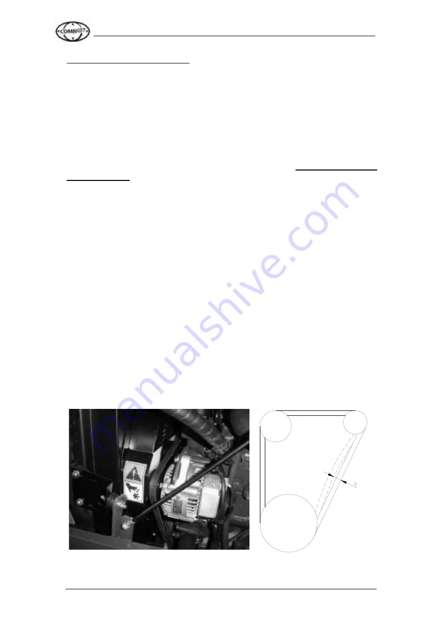
4.8:  Water Pump V- Belt 

The engine is kept cool via the coolant that is pumped round the cooling 
system. The water pump is powered by the Water pump V-belt. This is located 
on the engine as shown and checked as follows: 
 
Check the belt tension. Perform this when the engine IS NOT running. Press 
on the belt with a stick or rod. Ensure that the deflection is no more that 10mm 
to 12mm. If it is adjust the belt via the pulley adjusting bolts 
 
Check the belt condition: Inspect the condition of the belt. Be on the look out 
for signs of damage and wear. If the belt is damaged replace it immediately. 
Also check if the belt has sunk deeply into the pulley as this indicates 
excessive wear. Again replace the belt immediately if this is the case. 


https://www.forkliftpdfmanuals.com/

Summary of Contents for C10,000lbs

Page 1: ...inagh Co Monaghan Ireland Tel 353 47 80500 Fax 353 47 80501 E Mail info combilift com Combilift Ltd Operators service Manual Models C3500kg C4000kg C4500kg C4800kg C5000kg C5000XL C6000lbs C8000lbs C9...

Page 2: ...cts in the material handling industry Combilift Ltd The Purpose of this operators Manual This Manual contains all of the information you will require to operate your Combilift product safely and effic...

Page 3: ...in a manner to ensure the safe operation of the machine As can be seen the general principles of safe operation are presented before how the machine actual operates It is essential that the operators...

Page 4: ...ruck 3 5 3 6 Travelling Safely with a Load 3 7 3 7 Fuel Handling Storage 3 8 Section 4 Maintenance Service Information 4 1 4 1 Maintenance Schedule 4 1 4 2 Initial Service Conducted at 100 hours of Op...

Page 5: ...ash Relay Layout PLC Loom 5 6 5 7 Steering Hydraulic Functions Circuit 5 7 5 8 Hydraulic Drive Circuit 5 8 5 9 Standard Diesel Electric Circuit 5 9 5 10 Standard LPG Electric Circuit 5 12 5 11 Tier IV...

Page 6: ...Centre of Gravity CG The centre of gravity of any object is the single point about which the object is balanced in all directions Every object has a centre of gravity When the lift truck picks up a l...

Page 7: ...To keep the lift truck stable the centre of gravity must stay within the area of the lift truck represented by a triangle drawn between the three wheels If the centre of gravity moves forward of the...

Page 8: ...achine It is engraved with a number of details which are required by law These are The Trucks serial Number Its rated Capacity It s unladen weight It s date of manufacture The manufacturers name and a...

Page 9: ...onspicuous colour Low doorways should be marked with their clearance limits Operating in Hazardous Areas Standard trucks are not equipped to operate in cold stores flammable or explosive areas corrosi...

Page 10: ...have serious effects on the stability of the machine Electrical Storms Always discontinue operation of the truck in the event of an approaching electrical storm due to the associated risks of lightni...

Page 11: ...6 7 8 9 10 2 3 11 12 13 14 14 14 15 14 16 Now that the main components of the truck have been identified the next step is to identify the operator controls and how they function Component Layout 1 Fo...

Page 12: ...king brake on Direction Control Lever The directional control lever is the 5 postion lever located on the dash It can be set to forward reverse left right or neutral In order to select a direction of...

Page 13: ...icient oil in the sump Battery Charge Indicator Light This charging lamp indicates whether the alternator is charging the system or not With the key switch turned ON and the engine not running this re...

Page 14: ...e machine is in sideward mode When the front wheels are steered in to a certain position the carousel indicator light will illuminate It is at this point that the carousel mode is activated and the ma...

Page 15: ...ilift have a number of standard functions which can be fitted to the truck and operate off the auxiliary function lever These include Fork Positioner Side shift Telescopic forks Lift Drop Forks Take t...

Page 16: ...n turning When in sideward mode the rear wheel is fixed and the front wheels steer the truck When driving forwards turn steering wheel clockwise to turn truck clockwise turn steering wheel anti clockw...

Page 17: ...ate knob clockwise to increase and anti clockwise to reduce suspension stiffness C Using the height adjustment knob B adjust the yellow ride indicator C to the middle of the green area when seated D B...

Page 18: ...moving the panel through the access hole provided When the Combilift is not in use turn switch to OFF position by turning switch ANTI CLOCKWISE The Combilift will not start unless the switch is return...

Page 19: ...n of the Combilift ALWAYS wear the seat belt provided 3 2 Starting the Engine Diesel Engine Ensure that the parking brake is applied and that the directional control lever is in the neutral position I...

Page 20: ...nce the wheels are in position continuer as per the instructions Note The truck will NOT start unless the directional control lever is in the neutral position Note The starter must not be operated con...

Page 21: ...ls start to realign depress the accelerator pedal lightly to speed up the operation Once the mode change operation has finished and the light has illuminated in the dash follow the normal driving inst...

Page 22: ...neutral position Lower the forks till they are on the ground and tilt the mast forward If loaded retract the mast and rest the load on the platforms of the machine Leave the engine running Remove the...

Page 23: ...d slide the forks along the carriage When the forks are set to the desired position ensure that the keeper pin is engaged in a slot on the top of the fork carriage bar Loading in Normal Mode Lower rai...

Page 24: ...Placing a Load in Sideward Mode Drive the front of the machine as close to the placing area as possible Apply parking brake Lower raise the forks to the required height Extend mast Lower load Tilt for...

Page 25: ...r to the front of the machine before lifting To Double Fork a Load Raise the load slightly and retract the mast sufficiently to bring the load closer to the machine Lower the load ensuring that it is...

Page 26: ...ted and approved containers Containers MUST comply with current regulations and be clearly labelled When refuelling the truck always ensure that the hose nozzle or the can pourer is making good electr...

Page 27: ...n the vertical position to ensure that the pressure within the container is in the form of vapour not liquid Damage such as dents scrapes or gouges in the container may materially weaken the structure...

Page 28: ...Spark Plugs Check Engine Mounts Check Engine Mount Bolts Check Engine Idling Speed Change Both Diesel Fuel Filters Engine Belts Check for Wear Check Tension Check Cooling Fan Check Radiator Check Eng...

Page 29: ...The Visual Checks The Engine Checks The Operational Checks The details of the Inspection should be recorded on a Checklist like the one provided page 4 6 and a record of these inspections should be k...

Page 30: ...k is in good working order Check All the Fluid levels i e the engine oil the engine coolant and the hydraulic oil level Do not operate the truck if any of these fluid levels are below the min value re...

Page 31: ...applied by depressing the large red button on the dash Also ensure that the directional control lever is in the Neutral position Turn the key to the start position to start the engine and then releas...

Page 32: ...tart to realign for sideward mode When the wheels are fully in position sound the horn and release the parking brake The machine should now travel to the left Depress the inching pedal to stop the mac...

Page 33: ...tials OK OK OK OK OK OK OK OK OK OK OK OK OK OK OK OK OK OK OK OK OK OK OK OK OK OK OK OK OK OK OK OK OK OK OK OK OK OK OK OK OK OK OK OK OK OK OK OK OK OK OK OK OK OK Operational Checks OK OK OK OK O...

Page 34: ...bolts and fittings are tight Check radiator and if necessary clean fins Grease all points indicated on grease point chart Check all wheel nuts for tightness Check mast chains lubricate and adjust if r...

Page 35: ...litres Remove the drain plug and allow the system time to drain completely Once the system has drained completely dispose of the used oil in a safe and responsible manner Remove the engine oil filter...

Page 36: ...n of coolant additive must not fall below 40 If greater frost protection is required the coolant additive can be increased but only up to 60 frost protection to 40 C approx Any greater proportion of c...

Page 37: ...C to35 C 14 F to 77 F High Range 0 C to45 C 32 F to 113 F Castrol Hyspin AWH 32 AWH 46 AWH 68 B P Bartran HV 32 HV 46 HV 68 Esso Univis N 32 N 46 N 68 Mobil 13 M 15 M 16 M Shell Tellus oil T32 T46 T68...

Page 38: ...using Hand tighten the cartridge into position 6 Only use a genuine Combilift component Return Filter service Interval 500 Hours The return filter located on the top of the tank must be replaced at in...

Page 39: ...80 litres approx 4 6 Mast Maintenance Service Interval 250Hours Mast chains should be checked for elongation periodically and adjusted as required The chains must be adjusted so that the upper mast s...

Page 40: ...itions For this purpose use EP2 grease 4 8 Water Pump V Belt The engine is kept cool via the coolant that is pumped round the cooling system The water pump is powered by the Water pump V belt This is...

Page 41: ...the maintenance chart They are both accessed by extending the carriage forward and entering the frame of the machine 4 10 Air Filter Element Service Interval 500 Hours The air filter housing is locate...

Page 42: ...achine 4 11 Grease Point Chart The diagram below indicates all of the points on the Combilift that must be greased regularly A copy of this diagram is located in the operator compartment in the form o...

Page 43: ...e g driving the truck with a full load up an incline for a period of at least 5 minutes so that the exhaust gases reach the temperature required to burn off the soot However in some cases the DPF may...

Page 44: ...nt pump have a so called bypass function By turning the relevant screw item 1 the valve is so released that free oil circulation is made possible In order to bypass the motor screw in item 1 until it...

Page 45: ...head bolt as shown in the diagram with a nut fully inserted onto the bolt 3 Using a spacer similar to the one shown on the diagram tighten the bolt into the Brake assembly at the rear of the motor 4 W...

Page 46: ...taken the charge pressure should measure between 16 bar and 22 bar 230PSI and 320PSI Warning Ensure that the Machine is switched off until the pressure gauge has been attached before trying to read t...

Page 47: ...Cabin Cooling Fan Optional Radio 10 7 5 Horn 11 7 5 Optional Extra Solenoid e g Independent Fork Positioner 12 7 5 4 Way Switching Supply 13 7 5 Flashing Beacon 14 7 5 Optional Road Lights PLC Loom F...

Page 48: ...O S Manual 5 5 C4000 OM EN 08 5 5 Dash Relay Layout Relay Loom Below is a diagram of the layout of the relays inside the dash in the cabin of the Combilift truck with a relay loom OPTIONAL RELAYS http...

Page 49: ...t PLC Loom Below is a diagram of the layout of the relays inside the dash in the cabin of the Combilift truck with a PLC loom Relay Function 1 Starter 1a Glow Plug Timer 9 Steering Solenoid Supply 15...

Page 50: ...6 PORT DIVERTER VALVE STEERING Return Filter 25 Micron 90 Micron In Tank Strainer Filter STEERING MOTOR EF T P L R GEAR PUMP REAR STEERING CYLINDER RH STEERING CYLINDER LH STEERING CYLINDER TILT CYLI...

Page 51: ...h Valve Rear Wheel Motor LH WHEEL MOTOR RH WHEEL MOTOR Drive 4 Port Changeover Valve Legend Pump Suction Line Pump Drain Lines Brake Release Lines Motor Drive Lines Motor Drain Lines Control Pressure...

Page 52: ...XL O S Manual 5 9 C4000 OM EN 08 5 9 Standard Diesel Electric Circuit COMBILIFT LTD Title KUBOTA Diesel Electric Circuit Model C4000 Section 1 of 3 Revision Date 14 11 11 Drawn By David Murray https w...

Page 53: ...ft Ltd C4000 C5000XL O S Manual 5 10 C4000 OM EN 08 COMBILIFT LTD Title KUBOTA Diesel Electric Circuit Model C4000 Section 2 of 3 Revision Date 14 11 11 Drawn By David Murray https www forkliftpdfmanu...

Page 54: ...ft Ltd C4000 C5000XL O S Manual 5 11 C4000 OM EN 08 COMBILIFT LTD Title KUBOTA Diesel Electric Circuit Model C4000 Revision Date 14 11 11 Drawn By David Murray Section 3 of 3 https www forkliftpdfmanu...

Page 55: ...ED V BN m 3 R BN B R13 86 BK F1 S T G OIL 7 5 58 BN R 1 0 R 15 F7 R 86 85 RELAY 22 87 30 R Y R 15 F8 R 0 2 3 7 5 F9 BN ZD1 R15 87A WIPER WIPER FLASHING BEACON m m V R SUPPLY FOR RADIO 4 R 20 F6 R Y 7...

Page 56: ...O 0 ALLOW TURN TO 90 SOLENIOD FRONT WHEEL 90 ALLOW FRONT WHEEL 90 PROX REAR WHEEL AT 90 BN R9 87 R7 30 R8 30 R16 87 BN REFLEX STEERING SOLENOID FRONT WHEELS AT 90 LIGHTS ON DASH 90 ALLOW PROX 5 G PROX...

Page 57: ...7A 87 30 G BN 87 85 30 86 87A R 18 R 87 87A 85 86 30 BN DIVERTER SOL 10 30 BN G R Drawn By David Murray Revision Date 03 02 12 Section 3 of 3 54 30 58 F10 7 5 P BUTTON PUSH R 19 R 21 86 30 87 85 87A 8...

Page 58: ...Date 17 08 12 Drawn By David Murray Section 1 of 3 Title GM LPG Tier IV RELAYS Model C4000 C5000 C5000XL COMBILIFT LTD BUTTON PUSH P HORN 7 5 7 5 BN 20 7 5 15 R 7 5 NEG STARTER MOTOR BATTERY SWITCH IS...

Page 59: ...S Model C4000 C5000 C5000XL COMBILIFT LTD RELAY 6 BN O O 30 86 87A 85 87 R Y R13 86 O W TURN PUSH BK 30 87 RELAY 13 87A BK 86 85 BK Y 87A RELAY 5 BK 30 86 85 87 O TO BRAKE SWITCH 0 PROXIMITY FRONT WHE...

Page 60: ...12 F2 30 58 54 R17 86 R6 87 R 20 87A R Y R13 87 R11 30 R21 86 DIVERTER SOLENIOD R6 87 R20 87 10 30 DIVERTER SOL 30 87 GY BN BN 30 86 85 87 R 16 87A 30 87 BN BN 86 85 87A R 17 BN R G 86 85 G R 18 87A R...

Page 61: ...N 30 COMBILIFT LTD FUEL PUMP PULL HOLD SOLENOID STARTER SOLENOID DASH PANEL OIL GUAGE LOW FUEL GUAGE GLOW SPOTLIGHTS SPARE SPOTLIGHT TEMPERATURE GUAGE CAB HEATER CABIN INTERIOR LIGHT R WIPER CAB FAN W...

Page 62: ...16 PIN 15 PIN 14 PIN 11 R PIN 6 PIN 2 PIN 5 PIN 4 PIN 3 PIN 1 PIN 7 PIN 8 PIN 11 PIN 12 PIN 13 PIN 10 PIN 9 BN O BN O R O BN GY BN GR BN GR R BN BN BN 58 F2 54 R BN O GY O GR R R 85 87 R 9 86 30 87A F...

Page 63: ...e Main BN TO F2 R 1 GY BN 30 IGNITION SWITCH COMBILIFT LTD FCV 5 FUEL COMMANDER M 1 3 2 4 87 R 85 30 86 R R V B Y P 6 P R O V G GR V H 7 5 R R 58 54 F3 7 5 FUEL BN CHARGE R R OIL S T R 30 58 54 F1 SPA...

Page 64: ...4 30 PLUG X4 GY 7 5 F5 SWITCH FOOT BK BK BK BK BK W O O PIN 4 PIN 3 PIN 2 PIN 1 PIN 8 PIN 7 PIN 6 PIN 5 BK GY R R R 1A 87A 87 85 30 86 GR BK BN BN BL 1 BL BK BK BK BN BN 2 BL 3 BL BN 4 BL 5 FRONT WHEE...

Page 65: ...O OIL LIGHT METER HOUR G Y CHARGE GY R S G T V TEMP LIGHT MIL B LIGHT R BN MAST ve 30 STARTER MOTOR NEG M BATTERY ve SPOTLIGHTS O R HEIGHT WIPER CAB HEATER WIPER m 87 87A 85 m m 80 Fuse amp Main 87A 8...

Page 66: ...PIN 12 PIN 13 PIN 14 PIN 15 PIN 5 PIN 7 PIN 8 PIN 6 PIN 3 PIN 4 PIN 12 PIN 2 PIN 1 PIN 3 PIN 6 PIN 5 PIN 4 PLUG X3 1 PIN 13 PIN 14 PIN 17 PIN 18 PIN 15 PIN 16 W W BN BN R R BN BN GY PIN 5 PIN 9 PIN 6...

Page 67: ...GATIVE WIRES ARE NORMALLY BLUE OR BLACK DEPENDING ON WHAT UNIT IS BEING INVESTIGATED TAKE ALL NEGATIVES TO BE BLACK UNLESS STATED OTHERWISE BK BLACK BN BROWN BL BLUE R RED O ORANGE Y YELLOW GR GREEN V...

Page 68: ...ng System LED Status Meaning No LED No power Supply to PLC Flashing Green Fast PLC is not Programmed Flashing Green Slow PLC is Programmed Running Normally Static Green PLC is Programmed but not Runni...

Page 69: ...Negative for Board power Supply Blue Black X4 11 Reverse Signal From Direction Lever Brown X4 12 Left Signal From Direction Lever Green X4 13 Right Signal From Direction Lever Grey X4 14 Mast Height...

Page 70: ...1 16 Common Supply for Output 12 From fuse 4 Brown X5 1 17 Not Used n a X5 1 18 Zero Degree Solenoid 02 Grey Plug Pin Function Wire Colour X5 2 01 Not Used n a X5 2 02 Common Supply for Output 13 From...

Page 71: ...corresponding position If the joystick is malfunctioning the LED corresponding to the position will not light up Mode 2 Proximity Sensor Function Move Switch 2 to the ON Position Front Wheel 0 Degree...

Page 72: ...must only be used with the key turned on NOT with the engine running Forward Reverse 0 and 90 Solenoids Move Switch 4 to the ON Position to test Use the directional joystick to energise the solenoids...

Reviews: