background image


USER


MANUAL 

MPD-1611291-A


EXACT-V2 High End Rack Modulator / Exciter


3/10/2017 

                         MPD-1611291-A


Page 85/94 


(5)


Alarm due to primary clock reference loss is defined in a specific table. 


6.4.2


Contact the technical support 

Before contacting Hitachi-Comark  Technical Support Team,  please ensure 

you can provide them with following information: 

o


The type, hardware and software version and Serial number of the equipment 

o


The delivery date of the equipment 

o


Symptoms of the breakdown or a description of the problem 


HITACHI-COMARK CUSTOMER SUPPORT 

 
Tel. + 800-345-9295 
 

Email : 

[email protected]


The technical support team of Hitachi-Comark is present to answer your questions and 

try to understand the problem that may be encountering with your exciter. They will 

be able to help you to identify the problem or give you recommendations on how to 

return the unit to the factory.   


Summary of Contents for EXACT-V2

Page 1: ...Document Reference MPD 1611291 A...

Page 2: ...USER MANUAL MPD 1611291 A EXACT V2 High End Rack Modulator Exciter 3 10 2017 MPD 1611291 A Page 2 94...

Page 3: ...7 Output Processing 26 2 7 1 RF output muting and RF maintain features 26 2 7 2 Crest Factor Reduction Management 27 2 7 3 DAP Operation 30 2 8 Clock and Synchronization 32 2 8 1 GPS and clock manage...

Page 4: ...Configuration 67 5 Operation 71 5 1 Operation Generalities 73 5 1 1 Local Operation 73 5 1 2 Remote Operation 73 5 2 Embedded Web GUI Description 74 5 2 1 Requirements 74 5 2 2 Connection to EXACT V2...

Page 5: ...t any time without prior notice in order to improve design and supply the best possible product Copy warning This document includes some confidential information Its usage is limited to the owners of...

Page 6: ...20dBm output DAP and onboard GPS EXACT ATSC 3 VP EXACT ALP3 ATSC 3 0 software license Single PLP ALP software license 3 0 Document structure Chapter 1 System Overview This chapter gives an overview of...

Page 7: ...tandards html Table 1 Relevant standards for ATSC A6 Physical Layer Protocol A 322 http atsc org standards atsc 3 0 standards A7 Link Layer Protocol A 330 http atsc org standards atsc 3 0 standards Ta...

Page 8: ...USER MANUAL MPD 1611291 A EXACT V2 High End Rack Modulator Exciter 3 10 2017 MPD 1611291 A Page 8 94...

Page 9: ...USER MANUAL MPD 1611291 A EXACT V2 High End Rack Modulator Exciter 3 10 2017 MPD 1611291 A Page 9 94 1 System Overview...

Page 10: ...USER MANUAL MPD 1611291 A EXACT V2 High End Rack Modulator Exciter 3 10 2017 MPD 1611291 A Page 10 94...

Page 11: ...advantage of ATSC 3 0 technology The clock system has been carefully designed to reach a very low phase noise and it achieves the flexibility required to operate with different synchronization scheme...

Page 12: ...r all of the supported standards 1PPS and 10MHz external reference signals are available to reach a higher frequency accuracy An on board GPS receiver is also available and may be used for this purpos...

Page 13: ...USER MANUAL MPD 1611291 A EXACT V2 High End Rack Modulator Exciter 3 10 2017 MPD 1611291 A Page 13 94 2 Features Summary...

Page 14: ...USER MANUAL MPD 1611291 A EXACT V2 High End Rack Modulator Exciter 3 10 2017 MPD 1611291 A Page 14 94...

Page 15: ...o Null packet deletion ATSC framing and channel encoding o 8 VSB modulation core o Virtual Channel Table Update ATSC 3 0 Available from the S110 firmware version Digital Adaptive Non Linear Precorrec...

Page 16: ...ut power to ensure a stable system output power o Feedback input using direct adapted RF signal from amplifier output 10dBm or VDC signal from external power sensor Control and Management o Control an...

Page 17: ...being used the Equalizer should be turned off 2 3 Input Stream Management The Stream Management consists in routing the incoming data from the ASI SMPTE or the Ethernet interface towards the modulatio...

Page 18: ...on a programmable consecutive error threshold Once it is reached the stream selection switches automatically from the primary input to the secondary When the valid packets threshold is reached the str...

Page 19: ...st selects the desired standard using a simple command In ATSC 1 0 VCT Virtual Channel Table updates allows the user to change the major channel number and carrier frequency In ATSC 3 0 Available from...

Page 20: ...Linear precorrection for compensating the distortion due to the channel filter o Non linear precorrection in order to cope with the power amplifier distortion Digital precorrection can be adaptive run...

Page 21: ...nce and efficiency but also in order to save on technician time However when several RF signals are combined together adjacent channels the use of Linear DAP is not possible because the feedback signa...

Page 22: ...ter output To monitor the DAP process several statuses are available MER indicative measure PAPR indicative measure Measured left and right shoulder levels DAP elapsed time DAP status Active Stopped b...

Page 23: ...s stopped either by a timer value user configurable or manually stopped Figure 7 Single DAP mode operation SURVEY DAP In this mode the DAP process is started as the Single DAP mode Once the timer is r...

Page 24: ...n correct up to 3dB range 3dB to 3dB in amplitude and up to 3 s range 0 to 3 s in group delay With the feedback after the output filter an adaptive linear precorrection should automatically find the c...

Page 25: ...aptive Linear pre correction for sharp channel filters in ATSC 1 0 With specific sharp tuned filters the EXACT V2 Linear DAP algorithm could fail Generally the complexity of the channel filter is due...

Page 26: ...s available on the RF Monitor This output signal is the same as the main RF Out signal but with a lower level 20dB for the 0dBm exciter and 43dB for exciter with optional 20dBm internal preamp 2 7 1 R...

Page 27: ...receiver 2 7 2 Crest Factor Reduction Management PAPR Peak to Average Power Ratio issues are associated with high power peaks present in the signal By correctly managing PAPR reduction Crest Factor r...

Page 28: ...arameter impact on a signal Crest Factor setting 20dB No reduction Without any crest factor reduction the PAPR is 14 4dB Crest Factor setting 11dB After the adjustment PAPR is 10 8dB Note In the scree...

Page 29: ...e shows the variation of the shoulder level and the MER for different parameter values at a given crest factor When the Crest Factor Optimization parameter is increased the shoulder level becomes bett...

Page 30: ...lipping the signal out from the modulator 2 7 3 DAP Operation DAP stands for Digital Adaptive Precorrection it is an option allowing the user to run the EXACT V2 in a very high end mode in order to re...

Page 31: ...he Settings Tab the DAP mode can be enabled under Outputs Precorrections Non Linear DAP launch The same protocol as the basic DAP applies please refer to the previous chapter Note Enabling or disablin...

Page 32: ...board GPS or external 1PPS o Internal The module delivers a 10 MHz clock reference output signal and can also provide 1PPS if the user configures the 1PPS IN OUT connector as an output For VX20 x0x2...

Page 33: ...on the user s setup three cases can be considered 1 Working with external GPS signal reference using on board GPS receiver Figure 14 VX20 x0x2 clock synchronization GPS signal In this case the modula...

Page 34: ...available on the 1PPS I O interface This 1PPS reference signal is used for both temporal synchronization and 10 MHz PLL locking 3 Working with external 10 MHz and external 1PPS reference Figure 16 VX...

Page 35: ...s in any case 2 8 3 Loss of Reference Signal management LORS In SFN an accurate clock synchronization is very critical for ensuring a good SFN operation For this purpose the module implements the foll...

Page 36: ...s locked This optional functionality allows having the best accuracy on time reference PPS used for SFN systems The external references have to follow the recommendations specified in the interface de...

Page 37: ...module will mute if the Clock Synchro is still not OK Figure 18 Mute behavior LORS TimeOut is not reached 2 9 Power Measurements EXACT V2 provides the capability to measure the forwarded and reflected...

Page 38: ...ximum warning and alarm thresholds for both forward and reflected power can be set via WEB GUI by the user for error management and monitoring 2 10 Automatic Gain Control AGC EXACT V2 provides a built...

Page 39: ...USER MANUAL MPD 1611291 A EXACT V2 High End Rack Modulator Exciter 3 10 2017 MPD 1611291 A Page 39 94 3 EXACT V2 Rack...

Page 40: ...USER MANUAL MPD 1611291 A EXACT V2 High End Rack Modulator Exciter 3 10 2017 MPD 1611291 A Page 40 94...

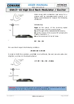
Page 41: ...nt panel Figure 22 Front panel overview The front panel is composed of an LCD screen display with six buttons four navigation buttons up down left and right arrows one OK green button and one Cancel R...

Page 42: ...terconnection with the exciter Please refer to the next section for a detailed description 3 2 Interface characteristics The product interface are as follows Stream input interfaces x 2 General Functi...

Page 43: ...erface Electrical Gigabit Port Data Control x 2 General Function Gigabit Ethernet Port Standards Ethernet IP Connector Name Gigabit1 Ctrl Gigabit2 Connector Type RJ 45 Type Input output Performances D...

Page 44: ...ystem Gain 10 dB Frequency 1575 42 MHz Figure 28 GPS antenna input Clock reference input x 1 General Function Frequency reference input Name 10 MHz_IN Connector BNC 50 Type Input Performances Frequenc...

Page 45: ...VTTL TTL input LVTTL output 50ns input tolerance Figure 31 1PPS reference input output x 1 General Function Standards Name Connector Type RF output ATSC 1 0 ATSC 3 0 RF N connector 50 Output Performan...

Page 46: ...0 ATSC 3 0 RF N connector 50 Output Performances Frequency Bandwidth Level ATSC 1 0 EVM Shoulders Spurious ATSC 3 0 MER Shoulder Spurious VHF 54 88 MHz VHF 170 216 MHz UHF 470 862 MHz 6 MHz 20 dBm 2...

Page 47: ...Type Output Performances Frequency See RF Output Level 20 dB relative to RFout Other Monitoring Output with OPT 20dB internal preamplifer x 1 General Function Monitoring output Standards ATSC 1 0 ATSC...

Page 48: ...Bm Max input level 5dBm before damage Return loss 13dB Figure 34 Feedback inputs Forward Power Measure Input AGC x 1 General Function Forward Power Measure Standards Name FWP In Connector SMA 50 High...

Page 49: ...ed Power Measure Standards Name RFP In Connector SMA 50 High impedance Type Input Performances RF input Frequency Depends on model Range 0 to 10dBm Precision 0 5dB typical Max Input Level 5dBm before...

Page 50: ...No parity 8 bits data 1 bit stop PIN Name Dir 1 RS232 Tx Out 2 Rfu 3 TOD Rx In 4 RS232 Rx In 5 GND 6 RS485 Rx In 7 RS485 Rx In 8 RS485 Tx Out 9 RS485 Tx Out Shield GND Figure 37 TOD RS232 Port The in...

Page 51: ...3_ Normally_Open Open when active alarm 5 GND cathode of the opto coupler diode 6 RELAY1_COM 7 RELAY2_ Normally_Open Open when active alarm 8 Anode of the opto coupler diode through 330 ohms resistor...

Page 52: ...econdary input is OK in auto mode Green static Primary input is OK 1 4 Output Green off no RF output module failure or mute condition Green static the RF output is available normal mode Green flashing...

Page 53: ...ntenna input This cable must be securely connected to the ground before switching on the equipment 3 5 Performances and technical characteristics 3 5 1 General characteristics Characteristics Typical...

Page 54: ...D LxD SMPTE 2022 MPEG TS Packet Length 188 bytes 3 5 3 Serial control interfaces Control interfaces Typical Value Comment RS232 Standard RS232 TX and RX signals only Limited to the use for TX control...

Page 55: ...t or Burst mode 188 bytes DVB ASI SMPTE 310M Maximum Useful Bit Rate 19 39 Mbps DVB ASI SMPTE 310M Max Input Jitter 100 ms Input Impedance 75 ohms Return Loss 15 dB up to 270 MHz TS or T2 MI Processin...

Page 56: ...ot level EXACT V2 EXACT V2 20dB at 20 dBm EXACT V2 20dB at 17 dBm Spurious 50 dBc Relative to the total power of the signal at nominal output power Amplitude Ripple 0 2 dB typical Group Delay Ripple 2...

Page 57: ...15 dBm Frequency 10 MHz 0 6 ppm External 1 PPS Reference Input Level LVTTL level 5 kohms Min Pulse Width 1 s 10 MHz Reference Output 0 dBm 3 dB 1 PPS Reference Output Level LVTTL Pulse Width 100 ns Ch...

Page 58: ...Full Temperature Range 5 10 9 0 50 C Tuning 0 6 ppm Short Term Stability 1 10 11 Over 1 s 10 s Aging 5 10 10 day 7 5 10 8 year 5 10 7 15 years Synchronization Cases Stability Aging External_10MHz_Loc...

Page 59: ...Step Size Accuracy 470 to 862 MHz 170 to 240 MHz 54 to 88 MHz 1 Hz 0 2 Hz Impedance 50 ohms Output Level Main Signal Stability Return Loss Attenuation Range Attenuation Step Monitoring Signal Relative...

Page 60: ...ion Linear Precorrection Amplitude Group Delay 32 points 3 dB 0 1 dB step 500 ns 10 ns step On the overall bandwidth Adaptive Precorrection Linear Adaptive Precorrection Amplitude Group Delay 3 dB 0 1...

Page 61: ...surement Bandwidth Full bandwidth Measurement Calibration Configurable Coupler Gain 0 to 100 0 dB Gain Step 0 1 dB Configurable Probe Offset 32768 mV to 32767 mV Offset Step 1 mV Configurable Probe Sl...

Page 62: ...product It Shows that we have checked that this product meets safety health or environmental requirements Is an indication of a product s compliance with legislation Allows the free movement of produ...

Page 63: ...USER MANUAL MPD 1611291 A EXACT V2 High End Rack Modulator Exciter 3 10 2017 MPD 1611291 A Page 63 94 4 EXACT V2 Installation...

Page 64: ...USER MANUAL MPD 1611291 A EXACT V2 High End Rack Modulator Exciter 3 10 2017 MPD 1611291 A Page 64 94...

Page 65: ...llation and Recommendations Install the unit in the appropriate location using four rack mounting screws not included as shown in the following figure Figure 40 Chassis installation Notes Mechanical m...

Page 66: ...he unit is integrated in an equipment cabinet sufficient space must be left on the right and left side of the unit to allow sufficient air flow 4 3 Wiring and Powering on Once fixed in a location the...

Page 67: ...ique address Address 192 168 0 211 Subnet 255 255 255 0 Gateway 192 168 0 254 DHCP OFF Gigabit 7 Front Panel Control not changed by default command MAC address module unique address Address 192 168 0...

Page 68: ...t OFF TS CleverSwitch Auto_Switch_Back Packet error threshold Packet valid threshold Enabled Disabled 5 80000 ATSC signalization 8 VSB ASI management unit Bit rate adaptation Enable Major Channel numb...

Page 69: ...Linear DAP Mode Non Linear DAP Mode Static DAP is disabled Static DAP is disabled Linear DAP Time_Out Non Linear DAP Time_Out 20 min 10 min Primary Clock Internal Secondary Clock Internal PPS Source O...

Page 70: ...Opening Triggers Output error Alarm error RF Switch Monitoring Disabled Transmitter Control Disabled Note different set of parameters are used for Single Carrier modulation ATSC and OFDM modulation f...

Page 71: ...USER MANUAL MPD 1611291 A EXACT V2 High End Rack Modulator Exciter 3 10 2017 MPD 1611291 A Page 71 94 5 Operation...

Page 72: ...USER MANUAL MPD 1611291 A EXACT V2 High End Rack Modulator Exciter 3 10 2017 MPD 1611291 A Page 72 94...

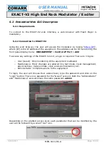
Page 73: ...eration The product can be controlled using any web browser It allows the user to control monitor and maintain the unit Below are the system requirements PC using a Pentium 1GHz or higher microprocess...

Page 74: ...IP Port Add To access any settings of the EXACT V2 unit a login is required There are 3 logins o User Guest Only monitoring of the equipment is allowed o Maintenance Minor changes are allowed like te...

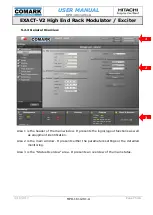
Page 75: ...neral Overview Area 1 is the header of the main window It presents the login logout functions as well as equipment identification Area 2 is the main window It presents either the parameters settings o...

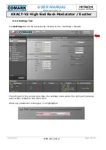
Page 76: ...1611291 A Page 76 94 5 2 4 Settings Tab The Settings tab can be accessed by clicking on the Settings header The left part of the screen describes the settings menu while the right part presents each...

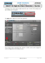
Page 77: ...77 94 A message in the main window header allows the user to verify if the settings have been modified and not applied The Apply button appears to confirm the application If any change must be discar...

Page 78: ...5 2 5 Monitoring Tab The Monitoring tab can be accessed clicking on the Monitoring header It is divided into 2 independent screens to allow the user to monitor two different blocks To select a block...

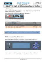
Page 79: ...or that occurred on the product To access to the Log File window please press the envelop Then the log file window is displayed 5 3 Front Panel Menu Description Main settings can be accessed from the...

Page 80: ...USER MANUAL MPD 1611291 A EXACT V2 High End Rack Modulator Exciter 3 10 2017 MPD 1611291 A Page 80 94...

Page 81: ...USER MANUAL MPD 1611291 A EXACT V2 High End Rack Modulator Exciter 3 10 2017 MPD 1611291 A Page 81 94 6 Maintenance Troubleshooting...

Page 82: ...USER MANUAL MPD 1611291 A EXACT V2 High End Rack Modulator Exciter 3 10 2017 MPD 1611291 A Page 82 94...

Page 83: ...ervice comarktv com or by calling 800 345 9295 For each software version available a unique file customer pack has to be provided by Hitachi Comark It is labeled as EXACT H100 S112 zip where EXACT V2...

Page 84: ...Output and Alarm LED indicators Name Description Power Green off power off Green fix power on Input Green off Primary input is not detected in manual mode or primary and secondary input is not detecte...

Page 85: ...o The type hardware and software version and Serial number of the equipment o The delivery date of the equipment o Symptoms of the breakdown or a description of the problem HITACHI COMARK CUSTOMER SU...

Page 86: ...USER MANUAL MPD 1611291 A EXACT V2 High End Rack Modulator Exciter 3 10 2017 MPD 1611291 A Page 86 94...

Page 87: ...USER MANUAL MPD 1611291 A EXACT V2 High End Rack Modulator Exciter 3 10 2017 MPD 1611291 A Page 87 94 Appendix A GPS Installation Recommendations...

Page 88: ...USER MANUAL MPD 1611291 A EXACT V2 High End Rack Modulator Exciter 3 10 2017 MPD 1611291 A Page 88 94...

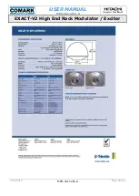
Page 89: ...the covered area Ga as the gain of the dedicated GPS antenna Gc as the losses of the several RF components cable connectors Gt as the total Gain of the RF chain Gt Ga Gc The user shall respect the fol...

Page 90: ...USER MANUAL MPD 1611291 A EXACT V2 High End Rack Modulator Exciter 3 10 2017 MPD 1611291 A Page 90 94...

Page 91: ...USER MANUAL MPD 1611291 A EXACT V2 High End Rack Modulator Exciter 3 10 2017 MPD 1611291 A Page 91 94 Appendix B Example of GPS Antenna...

Page 92: ...USER MANUAL MPD 1611291 A EXACT V2 High End Rack Modulator Exciter 3 10 2017 MPD 1611291 A Page 92 94...

Page 93: ...USER MANUAL MPD 1611291 A EXACT V2 High End Rack Modulator Exciter 3 10 2017 MPD 1611291 A Page 93 94...

Page 94: ...USER MANUAL MPD 1611291 A EXACT V2 High End Rack Modulator Exciter 3 10 2017 MPD 1611291 A Page 94 94...

Reviews: