48
AT THE END OF
THE WORK
At the end of the work, and before carrying out any type of
maintenance, perform the following operations:
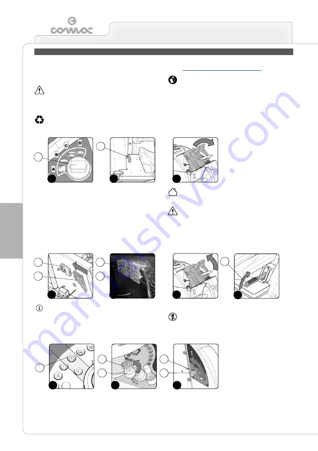
1. Select the i-drive program “transport” by rotating the knob (1) to
position “A” as shown in (
Fig.1
).
ATTENTION:
by rotating the i-drive selector to the transport
program, the brush head and squeegee will move to their idle
positions (raised above the floor).
2. Take the machine to the maintenance area.
ATTENTION:
the place designated for this operation must
comply with current environmental protection regulations.
AT THE END OF THE WORK
3. As soon as the machine has reached the maintenance area,
carry out the daily maintenance tasks indicated in the table in
the “
ATTENTION:
these operations must be carried out using
protective gloves to avoid any possible contact with the edges
or tips of metal objects.
4. After completing the tasks listed in the “RECOMMENDED
MAINTENANCE WORK” table, grip the handle (2) (
Fig.2
)
and raise the seat mounting plate to the maintenance position
(
Fig.3
).
5. Connect the battery connector (3) to the main system connector
(4) (
Fig.4A
- B versions).
6. Connect the alternator connector (5) to the main system
connector (4) (
Fig.4B
- G versions).
7. Grip the handle (2) (
Fig.2
) and lower the seat mounting plate to
the working position (
Fig.5
).
8. Sit on the driver’s seat.
9. Switch on the machine and take it to its designated storage
place.
ATTENTION:
park the machine in a covered place, on a flat
surface. There must be no objects near the machine that
could either damage it, or be damaged through contact with it.
ATTENTION:
machines powered with LPG must not be
parked lower than ground level, near openings that
communicate with underground rooms, or in poorly aired
places.
10. Engage the parking brake by moving the parking brake lever (6)
(at the side of the operator seat) in the direction shown by the
arrow (
Fig.6
).
ATTENTION:
the indicator light (7) relating to the engaged
parking brake will be activated on the control panel (
Fig.7
).
11. Bring the main switch (8) to “0”, turning the key (9) a quarter
turn to the right (
Fig.8A
- B versions) or (
Fig.8B
- G versions).
Remove the key from the instrument panel.
12. Get off the machine.
ATTENTION:
do not position your foot above the brush head
while the machine is coming down the ramp.
4A
4B
1
2
3
5
1
1
1
1
1
1
1
2
4
4
3
5
6
16
15A
15B
14
1
1
1
1
1
7
8
9
9
8
Summary of Contents for ULTRA 120 B-G
Page 2: ......
Page 7: ...7 36 72 102 6 9 10 110 107 106 75 5 76 74 58 7 59 7...
Page 9: ...9 103 4 56 31 43 109 15 3 98 22 65 24 108 19 34 35 23 68 44 63 64 99...
Page 10: ...10 2 94 17 101 96 105 69 12 11 18 73 40 97 95 104 42...
Page 68: ...68 NOTES...
Page 69: ...69 NOTES...
Page 70: ...70 NOTES...
Page 71: ......


