background image


Page 

52

 of 

62


Metro (Konica Head) 

 11. Switch OFF Procedure 

Note:

 Main MCB power must be ON. 

Follow these steps to learn the switch off procedure:  

Step 1:

 Perform the Nozzle Test to check Print Head nozzles status. 

Step 2:

  Clean the Print Heads, if required. 

Step 3:

 Remove the media from the machine. 

Step 4: 

Clean the Capping Station area and check the water in the Capping tray.  

Step 5: 

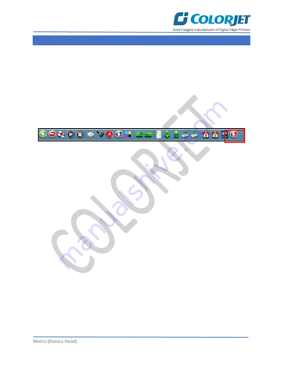
Click on the 

Auto Capping

 icon to engage capping station with the head plate using the Printer 

Manager, as shown below: 


Fig 72: Displaying the Auto Capping Option 

Note:

 Never move the carriage manually over elevated capping station. 

Step 6:

 Close the Printer Manager software.  

Step 7:

 Turn OFF the printer using the Power or Emergency button. 

Step 9:

 Cover all the printer.  

Now, the printer is switch off. 


Summary of Contents for METRO KONICA HEAD

Page 1: ......

Page 2: ...ca Head machine without anyone else assistance The information provided in this document ensures its uniqueness and language quality For safe and proper use of the product please read this manual care...

Page 3: ...on 13 Loading the Fabric 14 Filling Ink 16 5 Glue Coating 17 Glue Implementation 17 Stages of Glue Adhesive Process 17 Glue Process Preparation 19 Glue Coating Procedure 20 Glue Removing Preparation 2...

Page 4: ...PI and Mode 45 Pausing and Canceling Printing 45 9 Head Cleaning 46 Head Blotting 46 Setting Wiping and Capping Height 47 Head Purging 47 Head Spraying 48 10 Cleaning Tub Unit 49 Cleaning Tub Unit 49...

Page 5: ...ative Pressure Drop Not Working 58 Fabric Not Sticking to Belt 58 Print Not Drying Ink Marks on Back of the Fabric 58 Ink Not Filling 59 Fabric Not Peeling OFF 59 Impression of ink on plain fabric 59...

Page 6: ...familiar with the terminologies of printer and printing business Thus this document is designed to facilitate both types of users 2 Machine Specification Machine specifications are shown as below MET...

Page 7: ...ying the Front View of the Machine Table 1 Different Part of the Printer 1 Left Cover 2 Front Cover 3 Signal Lamp 4 Right Cover 5 Touch Screen 6 Emergency Button 7 Power Button 8 HMI 9 Washing System...

Page 8: ...the machine is shown in the image below Fig 2 Displaying the Back View of the Machine Table 2 Different Part of the Printer 1 Emergency Button 2 Ink Tanks 3 Ink Inlet 4 Pressure Roller 5 Jetting Pump...

Page 9: ...ws of Feeder The Front Side of the Feeder is shown in the image below Fig 3 Displaying the Front View of the Feeder Table 3 Different Part of the Printer 1 Fabric Spreading Roller 2 Supply Air Shaft 3...

Page 10: ...ide of the Feeder is shown in the image below Fig 4 Displaying the Back View of the Feeder Table 4 Different Part of the Printer 1 Fabric Spreading Roller 2 Power Control Unit 3 Supply Motor 4 Leveler...

Page 11: ...image below Fig 5 Displaying the Front View of the Dryer Table 5 Different Part of the Printer 1 Guiding Bar 2 Guiding Bar 3 Exhaust Fuel 4 IR Heater 5 Emergency Button 6 PID Controller 7 PID Control...

Page 12: ...Konica Head The back side of the Dryer is shown in the image below Fig 6 Displaying the Back View of the Dryer Table 6 Different Part of the Printer 1 Exhaust Fuel 2 IR Heater 3 Guiding Bar 4 MCB Heat...

Page 13: ...capping X axis gets initialized Step 6 Capping start verifying the maximum up limit and stay on defined position Step 7 Wiper unit gets activated and starts the initialization process Step 8 Refill wa...

Page 14: ...igin to specify the printing starting position Now the printer is ready for printing Signal Lamp Description Signal Lamp description is given as below Color Light of Steadily Flashing Light Remarks Re...

Page 15: ...e unlock position of Safety Chuk and Shaft get matched as shown below Fig 9 Displaying the Unlock Position Step 3 Push the Safety Chuk to remove the shaft Step 4 Insert the shaft into the fabric roll...

Page 16: ...Page 15 of 62 Metro Konica Head Step 6 Load the media as per the path given below Fig 11 Displaying the Fabric Path Now the fabric gets loaded...

Page 17: ...the image below Fig 12 Displaying the Main Ink Tank Points need to remember The Main Ink Tanks are located at the back of the printer The capacity of ink main tank is 10Litre Ink in the Main tanks is...

Page 18: ...eans it s time for a coat of the Perma Solvtek This is used either to dilute the adhesives or to complete removal of the all adhesive layers The following are the two main reasons for removing all the...

Page 19: ...als as base and it harms the belt or adversely affects the life of the Printing Blanket Conveyor Belt RECOMMENDED Alcohol Methyl alcohol Ethyl alcohol Isopropyl alcohol Ester Butyl acetate Ethyl aceta...

Page 20: ...t fans ready Step 2 Lift up the Press Roller and remove the fabric if any Step 3 Run the Wash Cycle from HMI simultaneously belt can be cleaned by wiping with cloth Fig 14 Running the Wash Cycle Step...

Page 21: ...ay render the coat unsuitable for use and complete process may be required to be repeated 3 persons will be required for this process Follow these steps to start the glue coating process Step 1 Put th...

Page 22: ...hould start spraying the cleaner liquid continuously till the end Fig 19 Spraying the Cleaner Liquid Step 8 Later the cleaner liquid spraying should be done throughout the belt until the remaining glu...

Page 23: ...glue Prepare proper ventilators Wear proper safety armament to prevent from touching glue and cleaner Put cover sheets on under belt printer front and rear to protect them from dropped glue and cleane...

Page 24: ...nutes to dissolve glue Step 5 Wipe dissolved glue and cleaner by wipe clothes Step 6 After wiping out the part turn the belt and repeat wiping until wipe out over all Fig 22 Wiping the Glue Step 7 Spr...

Page 25: ...d Step 9 After clean up the part turn belt and repeat cleaning until clean up over all Remove cover sheet which covers washing unit Step 10 Finally remove remained cover sheets and keep the belt dry F...

Page 26: ...ler in reverse and forward direction enable the Washing Unit Switch ON or OFF the Feeder Unit and Take Up etc ALARM Switch ON or OFF the alarm unit BELT MOVEMENT Move the belt in reverse and forward d...

Page 27: ...ervice which you want to disable Refer to Fig 27 Controlling Belt Movement To control the belt motion select the BELT MOVEMENT icon from the MAIN MENU screen Refer to Fig 25 The BELT MOVEMENT screen a...

Page 28: ...on of washing tub select the TUB DOWN icon from the WASHING SYSTEM screen The WASHING SYSTEM screen appears as shown below Fig 30 Displaying the WASHING UNIT Screen After setting the tub position swit...

Page 29: ...above screen change the washing system switch ON or OFF FEEDER and SPREADER ROLLER and print dryer settings READY TO PRINT Option The READY TO PRINT enables to make the machine in the ready to print s...

Page 30: ...directly issue the print command stop the print resume the print and start the print from beginning On touching the ONLINE icon the following screen appears Fig 33 Displaying the ONLINE Mode Screen To...

Page 31: ...Job Delete Job Print Job Pause or resume Abort job Check nozzle Move left Move right Move forward Move backward Z Move Down Z Move Up Move carriage to origin Move carriage to origin Y Move carriage t...

Page 32: ...Page 31 of 62 Metro Konica Head Setting Menu The Setting window with the Printer tab is shown in the below image Fig 35 Displaying the Setting Window...

Page 33: ...ca Head The Move tab is shown in the image below Fig 36 Displaying the Move Tab The Preference Tab is shown in the image below Fig 37 Displaying the Preference Tab Note Unit value can be changed using...

Page 34: ...or to feed password of the printer On clicking Password option under the Tools menu the Password window appears with two options viz Time Password and Language Password Let s learn to feed password in...

Page 35: ...h of the password field must be of 16 digits Step 3 After feeding the passwords click on the Set button in front of both the options Refer to Fig 40 Step 4 Click on the Exit button to close the Passwo...

Page 36: ...the printing by clicking on the left and right buttons on the Quick Access Toolbar as shown below Fig 42 Adjusting the Carriage Position Step 2 After positioning the carriage click on the Set print or...

Page 37: ...ation one by one in details Note Mechanical checks are performed by service engineer thus these checks and their description are not included in user manual Opening the Calibrating Wizard Print Heads...

Page 38: ...lt set value It has to be performed for each print mode whichever is required Let s discuss each type of horizontal test one by one Bi direction Calibration Bi directional calibration is performed to...

Page 39: ...to Left Calibrations Left to Right Calibration is performed to achieve dot placement accuracy of all colors Black Cyan and Yellow with respect to Magenta during the carriage s left to right print swe...

Page 40: ...the fabric forward for the next pass This movement of fabric is called a step The distance by which the fabric is moved is called the step size and it has to be accurate Step size errors cause horizon...

Page 41: ...Refer to Fig 51 Step 3 Click on the icon Refer to Fig 51 on the Step Calibration window The correction value result will be reflected in the Step field Refer to Fig 51 The same step value will also b...

Page 42: ...steps to add jobs in the Job List area Step 1 Click on the Add Job button on the Quick Access Toolbar as shown below Fig 53 Clicking on the Add Job Button The Open window appears on the screen Step 2...

Page 43: ...umber of passes can be viewed in the Job Information area User can also add a job simply by right clicking on the Job List area and selecting the Add Job option from the context menu as shown below Fi...

Page 44: ...57 Selecting the Edit Job Option The Edit Job Form appears with the list of options viz Clip Reverse Print and Tile Step 4 Select the desired checkbox in front of the Clip Reverse Print and Tile opti...

Page 45: ...the color corrections in the image You can print an image on the selected media simply by clicking on the Print Job button available on the Quick Access Toolbar as shown below Fig 59 Issuing the Print...

Page 46: ...le Print DPI Print Passes 600x600 1 600x1200 2 600x1800 3 600x2400 4 Pausing and Canceling Printing If you find any defect during the printing process you can immediately pause or cancel the current p...

Page 47: ...nting result and quality In Metro auto wiping option is available to clean the head surface area The Auto Wiping option is shown in the image below Fig 63 Displaying the Auto Wiping Option On clicking...

Page 48: ...ht Using the Setting window user can set the wipping and capping height by updating values in the Z Clean Pos and Z Wet Pos list boxes as shown below Fig 65 Setting Wiping and Capping Height Head Purg...

Page 49: ...re blocked This method is used to avoid mixing of colors When heads are sprayed all the nozzles are actuated at a high rate which helps in opening up dry nozzles of the printer To perform head sprayin...

Page 50: ...ps to clean the tub unit Step 1 Lower down the tub using HMI and follow the below path Main Menu Ready To Print Washing System Tub Out as shown below Fig 68 Issuing the Tub Out Command Step 2 Loose Al...

Page 51: ...tro Konica Head Now the tub comes out and user can start the maintenance work as shown below Fig 70 Cleaning Tub After completing the cleaning reversely follow the above given steps to fix the tub Bru...

Page 52: ...Konica Head Cleaning Jetting Nozzle Jetting Nozzles are shown as below Fig 71 Displaying the Jetting Nozzles To clean jetting nozzles remove them using the 10mm spanner and clean it to remove any blo...

Page 53: ...hine Step 4 Clean the Capping Station area and check the water in the Capping tray Step 5 Click on the Auto Capping icon to engage capping station with the head plate using the Printer Manager as show...

Page 54: ...of related parts 10 It s time for tub maintenance if a Jetting pipe have choked nozzles b When brush roller is filled with threads c When sponge roller is not moving and has become slippery 11 When b...

Page 55: ...se the nozzle blockage Humidifier has to be always in working condition which keeps the head nozzles wet and open Carriage cover should always be fixed to protect electronics after head maintenance Do...

Page 56: ...to be checked from time to time for its adhesive strength Whenever required fresh coating is to be done Also wiping with wet cloth can clean the previous coating layer sometimes Precautions If the glu...

Page 57: ...while Jetting Pump is OFF Don t run the Wash Cycle until the glue gets dry after glue coating wait for 3 or 4 hours Always use the cleaned RO processed water for washing system Don t forget to clamp t...

Page 58: ...B free space in hard disk Remove unwanted programs and old ripped files from the computer to improve the speed of printing Monthly Maintenance LM guide should be wiped monthly Cleaning the floor parti...

Page 59: ...dryer is OFF Belt Shifted Shifting is not monitored and arrested through the Shifting Control wheel Shifting control knob is rotated incorrectly or excessive Negative Pressure Drop Not Working Adjust...

Page 60: ...sticked over the belt Brush is congested with fabric threads and not uprooting the threads from the belt Printer Manager Not Showing Ready USB is disconnected from computer or loosely connected Print...

Page 61: ...Page 60 of 62 Metro Konica Head Lines in Prints Nozzle blocked in heads check nozzle test Incorrect feed step calibration required Belt motor coupling loose...

Page 62: ......

Page 63: ...For Any Query Please Contact Us www colorjetgroup com Call us on 91 120 4548195 Email on info colorjetgroup com For Ink Enquiry sales colorjetgroup com...

Reviews: