background image


Cohu Electronics 


5930 Series Thermal Camera User's Manual 


Cohu Electronics 

P

AGE

 9 

OF

 17 

3912 Calle Fortunada 

San Diego, CA 92123-1827 

Phone: 858-277-6700 

Fax: 858-277-0221 


2.3 

Electrostatic Discharge (ESD) Precautions. 

The installation procedures in this user's manual do not require entry into the Enclosure of the 
Camera.  However in the event that the camera needs to be opened as directed by Cohu 
Electronics , the following ESD precautions should be followed: 



Use a conductive pad on whatever work space used. 



Connect the conductive pad to earth ground through a 1M

 resistor. 



Use a wrist strap connected to earth ground through a 1M

 resistor when working with the 

equipment. 



Maintain the relative humidity above 30%.  Working on this circuitry with a relative humidity 
below 30% requires more extreme ESD precautions not specified in this document. 



Use antistatic bags to store and transport any electronic components or circuit board 
assemblies removed from this Camera.  Use new antistatic bags as old antistatic bags can 
lose their static protection after use. 

2.4 

Tripod Mounting Interface 

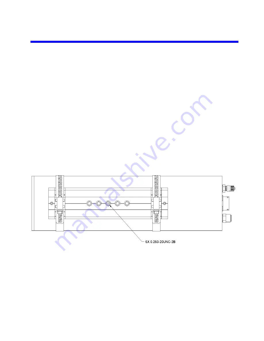
The camera has a tripod mounting plate clamped to the bottom of the Camera.  The Tripod mount 
has five mounting threads (0.250-20UNC-2B) separated as shown in Figure 4.  This provides two 
center-to-center mountings, being 1.75

 and 1

 bolt patterns.  Insure the mounting arm/fixture 

supports one of these mounting bolt patterns. 


Figure 4 - Tripod Mounting Locations 

2.5 

Main Rear Panel Signal Connector 

The main signal input/output connector is located on the rear panel of the Camera as shown in 
Figure 5. 

Summary of Contents for 5935-1000/T100

Page 1: ...Camera User s Manual Cohu Electronics PAGE 1 OF 17 3912 Calle Fortunada San Diego CA 92123 1827 Phone 858 277 6700 Fax 858 277 0221 Figure 1 5935 1000 T100 Thermal Camera with 100mm Lens Installed Tec...

Page 2: ...2 Installation 8 2 1 Unpacking and Receiving Inspection 8 2 2 Lens Cleaning 8 2 3 Electrostatic Discharge ESD Precautions 9 2 4 Tripod Mounting Interface 9 2 5 Main Rear Panel Signal Connector 9 2 5 1...

Page 3: ...3 Camera Support Functions 5 Table 4 Fixed Focus Lenses 7 Table 5 Camera Performance 7 Table 6 Main Signal Pin Descriptions 10 Table 7 Digital Signal Pin Descriptions 11 Table 8 Environmental Cable Cl...

Page 4: ...lt in TE cooler The FPA incorporates internal thermal reference detectors that provide compensation for thermal drift and noise 1 2 Hardware Description The camera electronics are comprised of four ma...

Page 5: ...s Digitized FPA Video NUC Corrected Video Pixel Replaced Video Intensity Transform Video PCB Size 2 x 2 1 2 3 Camera Support PCB The camera support PCB provides all the power supply conditioning and c...

Page 6: ...rol Typically only a few settings or adjustments require attention once the Camera is embedded into a specific application A complete list of adjustable settings and software features can be found in...

Page 7: ...10 5 T100 100mm 36 inches 9 x 7 T200 200mm 120 inches 4 5 x 3 5 The front lens plate has a machined groove designed specifically to interface to an O Ring installed on the f 1 4 lenses to ensure the w...

Page 8: ...nd Receiving Inspection The camera was tested and carefully packed at Cohu Electronics Upon acceptance by the carrier they should assume responsibility for its safe arrival Should you receive this ite...

Page 9: ...ive humidity above 30 Working on this circuitry with a relative humidity below 30 requires more extreme ESD precautions not specified in this document Use antistatic bags to store and transport any el...

Page 10: ...le 6 Main Signal Pin Descriptions Pin Number s Direction Signal Name Signal Description G Input Chassis Chassis Ground U Input AC Line AC Line high side power input Camera will function on voltage inp...

Page 11: ...ptions Pin Number s Direction Signal Name Signal Description 6 Input ExtClk Positive LVDS external clock input NTSC 49 09090 MHz PAL 59 00000 MHz 7 Input ExtClk Negative LVDS external clock input NTSC...

Page 12: ...7mm E3 1031 2 6 2 5 7 6 2mm E3 1031 2 6 7 6 2 6 7mm 2 7 Power Input Selection The camera input power is specified by model configuration when originally ordered from Cohu Electronics and is delivered...

Page 13: ...Input Selection 3 Camera Software Features The Camera is equipped with a multitude of operational and configuration settings See Table 9 for all the software features available in this Camera Table 9...

Page 14: ...emperature M Contact Lumitron for ADC to temperature equation Two Available Internal Remote Temperatures M Contact Lumitron for ADC to temperature equation Calibration Flag Temperature M Contact Lumit...

Page 15: ...ion of any FPGA registers is not suggested except for advanced users Changes may prevent camera from operating properly Access to DSP Memory C M Read Write access reserved for specific OEM s Access to...

Page 16: ...meras Cameras utilizing extended infrared extended IR sensors found to exceed acceptable white blemish specifications within one month of delivery shall be repaired without charge This warranty does n...

Reviews: