background image

Page 4 of 12

fearless

Installation guide

3. Positioning of the system

At the beginning of the installation, you need to find the correct position for your 
3D sensor in the room. Please note that the sensor can be easily adjusted in two 
directions by turning it carefully.

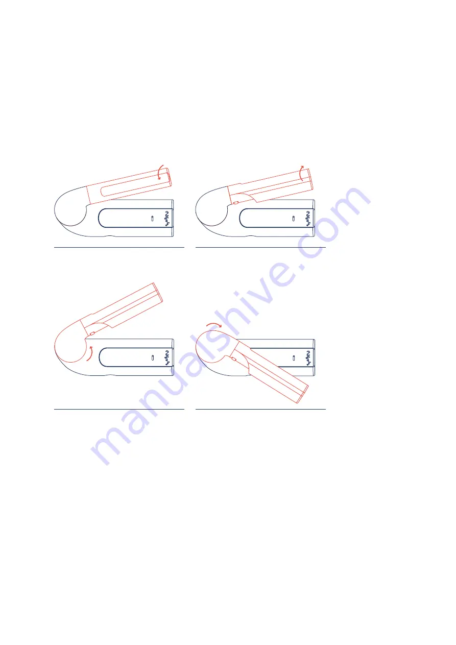
The sensor can be adjusted accordingly by 
carefully turning the front panel.

The front part can be turned in both directions.

The entire sensor part can also be turned in both 
directions.

To rotate the entire sensor part, gently pull it out 
of its anchorage, turn it to the correct position and 
release it again until it clicks into place.

Identify the main area that should be covered. This is the free area with a 
particularly high risk of falling. The sensor can be mounted 

on the wall or on 

the ceiling.

 We recommend mounting the sensor on the ceiling, as the sensor 

orientation is more flexible. 

Summary of Contents for fearless

Page 1: ...cogvis at fearless Installation guide...

Page 2: ...4 Mounting 6 5 Software setup 9 Step 1 Start setup 9 Step 2 WiFi setup 10 Step 3 Check status 10 Step 4 Alignment and Calibration 11 Step 5 Operation 11 6 Connection to existing call systems 12 1 Gene...

Page 3: ...allation USB power supply and 5m connection cable fearless sensor 4 dowels and 4 screws The fearless sensor consists of 2 parts the metal base part with the already mounted board evaluation unit and t...

Page 4: ...he front panel The front part can be turned in both directions The entire sensor part can also be turned in both directions To rotate the entire sensor part gently pull it out of its anchorage turn it...

Page 5: ...ion Sample illustrations for the sensor position The following example rooms will help you to find the correct sensor position The color coded area represents the area that the sensor covers approxima...

Page 6: ...ossible a Standard ceiling mounting b Standard wall mounting c Ceiling mounting 180 degrees rotation if required d Wall mounting 180 degree rotation if necessary Please note that in this case you must...

Page 7: ...the sensor is positioned opposite the windows Maximum range 7 meters When mounting please use the four included dowels and screws Never touch the board only the metal plate Never touch the board Only...

Page 8: ...f the board is at the corresponding opening of the housing Now mount the housing onto the metal plate as follows Now continue with software setup Step 1 Place the housing from bottom to top Make sure...

Page 9: ...per side of the white housing for approx 8 seconds see illustration and then restart the setup procedure Setup problems Press the button for 8 seconds Step 1 Start setup Start the device by connecting...

Page 10: ...n on the housing for 1 3 seconds Then as described in step 1 search for the appropriate wireless network and repeat the following steps Step 3 Check status Now please check the status of your device T...

Page 11: ...lign it if necessary and click on Restart on the platform Now check the image according to step 4 Calibration visualization Change of the sensor image on the platform if necessary under Initialization...

Page 12: ...l connection cable you are welcome to order them from us To connect the system to the existing call system please consider the following brief instructions 1 Trigger a test alarm on the fearless platf...

Reviews: