background image

Page 3 of 12

fearless

Installation guide

Note the following

—›   Please make sure that you have a good WiFi coverage in the room before 

installation.

—›   Please make sure that your WiFi connection can be established directly by 

entering the WiFi name and password and no login via an additional login  
form is required.  

—›   Keep your login data ready for the fearless platform and make sure,  

a smartphone or laptop is available. 

—›   In addition, never put the sensor into operation when it is not mounted.

2. Package contents and preparation

Package contents for the fearless system for on-site installation: 
—›   USB power supply and 5 m connection cable 
—›  fearless sensor
—›  4 dowels and 4 screws

The 

fearless sensor consists of 2 parts:

 the 

metal base part

 with the already 

mounted board (evaluation unit) and the 

white plastic sensor housing.


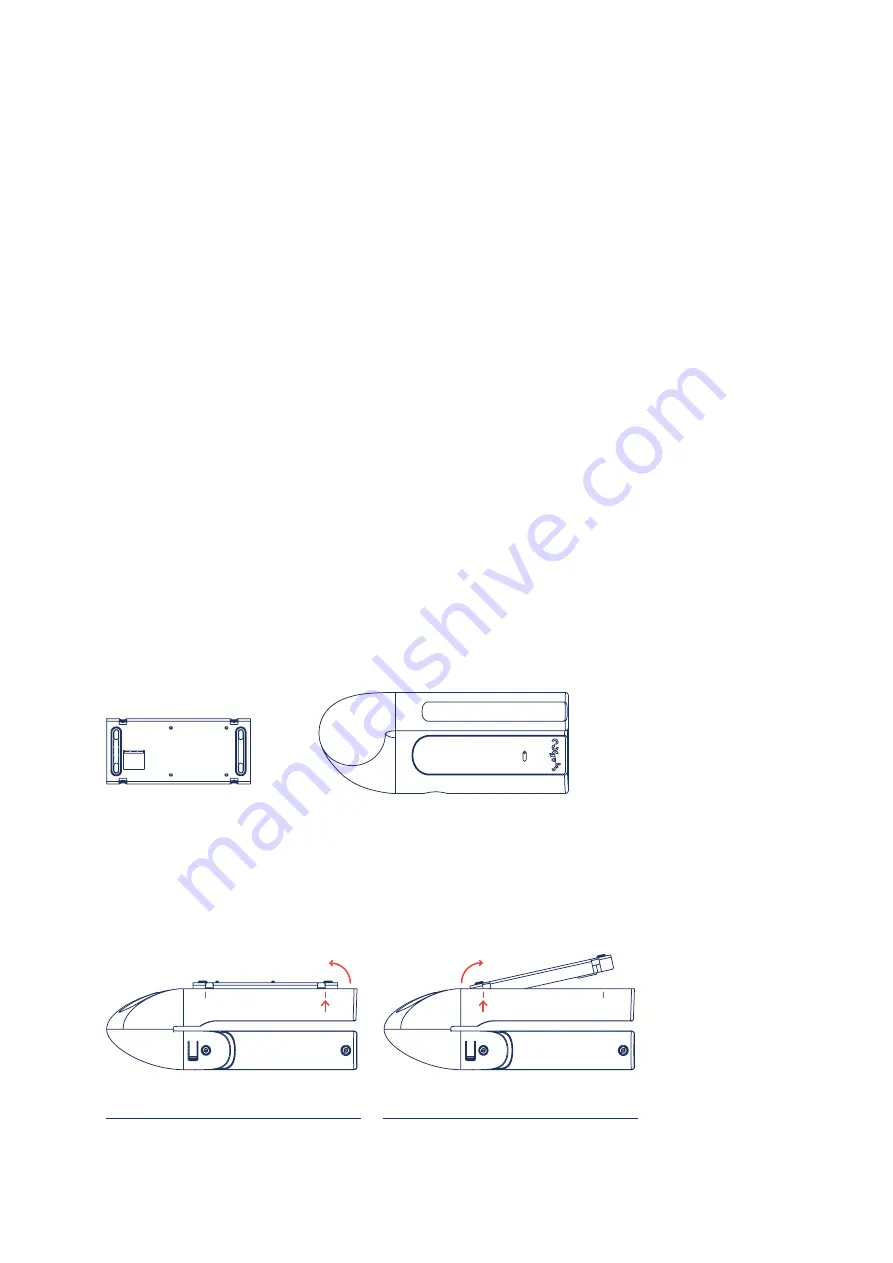
The sensor housing is connected to the base unit through 4 clamps. 

Both parts 

can be released from each other by slight pressure from the outside (along the 
lower edge of the sensor unit in the area of the clamps). Please note the following 
illustration:

Metal base part

Plastic sensor housing

Step 1: 

Press on both sides of the outer edge of the 

unit in the area of the clamps and gently push the 
base out on one side.

Step 2: 

If the first side is released, apply the same 

principle to the second side and remove the base 
completely from the housing.

Summary of Contents for fearless

Page 1: ...cogvis at fearless Installation guide...

Page 2: ...4 Mounting 6 5 Software setup 9 Step 1 Start setup 9 Step 2 WiFi setup 10 Step 3 Check status 10 Step 4 Alignment and Calibration 11 Step 5 Operation 11 6 Connection to existing call systems 12 1 Gene...

Page 3: ...allation USB power supply and 5m connection cable fearless sensor 4 dowels and 4 screws The fearless sensor consists of 2 parts the metal base part with the already mounted board evaluation unit and t...

Page 4: ...he front panel The front part can be turned in both directions The entire sensor part can also be turned in both directions To rotate the entire sensor part gently pull it out of its anchorage turn it...

Page 5: ...ion Sample illustrations for the sensor position The following example rooms will help you to find the correct sensor position The color coded area represents the area that the sensor covers approxima...

Page 6: ...ossible a Standard ceiling mounting b Standard wall mounting c Ceiling mounting 180 degrees rotation if required d Wall mounting 180 degree rotation if necessary Please note that in this case you must...

Page 7: ...the sensor is positioned opposite the windows Maximum range 7 meters When mounting please use the four included dowels and screws Never touch the board only the metal plate Never touch the board Only...

Page 8: ...f the board is at the corresponding opening of the housing Now mount the housing onto the metal plate as follows Now continue with software setup Step 1 Place the housing from bottom to top Make sure...

Page 9: ...per side of the white housing for approx 8 seconds see illustration and then restart the setup procedure Setup problems Press the button for 8 seconds Step 1 Start setup Start the device by connecting...

Page 10: ...n on the housing for 1 3 seconds Then as described in step 1 search for the appropriate wireless network and repeat the following steps Step 3 Check status Now please check the status of your device T...

Page 11: ...lign it if necessary and click on Restart on the platform Now check the image according to step 4 Calibration visualization Change of the sensor image on the platform if necessary under Initialization...

Page 12: ...l connection cable you are welcome to order them from us To connect the system to the existing call system please consider the following brief instructions 1 Trigger a test alarm on the fearless platf...

Reviews: