S E T U P
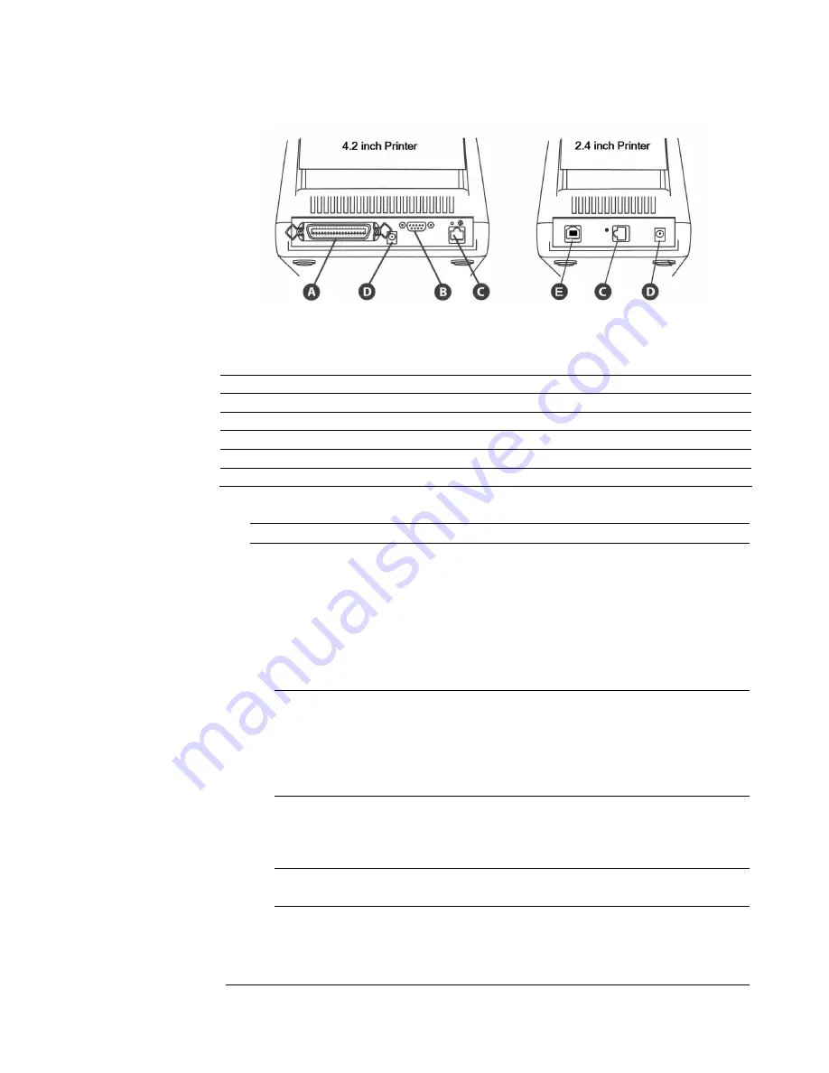
Figure 3-2. Advantage RFID Thermal Printer (Rear View) Connections
and Power
Connector Use
A - Parallel port (optional)
Parallel data communications port
B - Serial port (RS232)
Serial data communications port
C - Ethernet connector (optional)
Ethernet communications port for network connectivity
D - POWER connector
Connection for power adapter
E – Universal Serial Bus (USB) port
USB communications port
NOTE:
Printer port options are dependent upon printer model.
Connecting Power and Cables
The following steps describe how to connect power and data cables.
1.
Connect a data cable (parallel, serial, USB, or Ethernet) to the
connector on the back of the printer.
NOTE:
A null modem cable is required for serial connections. Do NOT use
a standard serial cable.
For parallel connections, use a standard, non-bidirectional (Centronix
®
)
cable. The parallel port must be configured as an LPT port, not an ECP
port.
2.
Connect the cable from the power supply to the power connector
on the back of the printer.
IMPORTANT!
Use only the 19VAC power supply provided with the printer.
Copyright © 2004, Cognitive.
9


