background image


Rev 3 Coffee Crafters -| Maintenance and Troubleshooting 


37 

Mast Tubing Maintenance 


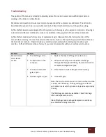
Replace Mast Flex Ducting when dirty. This can be check by removing the duct on the upper chaff collector as 
indicated in the image above. 


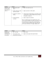
Taking the Hopper Off 

 
Rotate hopper 90 degrees to the left and lift slightly and pull towards you to remove the hopper. 
*Note- 

it’s easier to look behind the hopper to see the key rotating into removal position.


Remove this ducting 
to see the interior of 
the flex tube

Summary of Contents for Artisan X-e Base

Page 1: ...tisan X e Base Model 10lb Fluid Bed Coffee Roaster Manual 708 S Clearwater Loop Ste 105 Post Falls ID 83854 www coffeecrafters com Phone 509 228 6916 info coffeecrafters com Copyright 2020 Coffee Crafters LLC All Rights Reserved ...

Page 2: ...er Hopper Support 10 Installing Hood Support Mast 11 Installing Hood 12 Installing The Hopper 13 Installing The Chaff Guard 14 Thermometer 15 Mounting the Thermometer Brakcet To Hopper Screen 16 Thermocouple Probe Positioning 17 Installing Condiut and Cord Routing 20 Installing Exhaust Blower 21 Flex Hose 24 Installing Light Kit 25 Temperature Switch 26 Helpful Tips 27 Roasting 28 Roast Coffee In ...

Page 3: ...ing 37 Taking The Hopper Off 37 Exhaust Tubing 38 Exterior Surfaces 38 Troubleshooting 39 Exhaust Blower Losing Suction 39 Bean Loft Motor Won t Run 40 Both Heat Elements Won t Turn On 42 Bean Loft Motor Runs At Full Speed Only 42 Both Elements Running But Roasts Take Too Long 42 Troubleshooting Figure 1 1 43 Troubleshooting Figure 1 3 44 Troubleshooting Figure 1 4 SSR Connections 45 Troubleshooti...

Page 4: ...e we have received from customers and at coffee shows I think we succeeded Coffee Crafters designed and began selling its Artisan V fluid bed coffee roaster in August 2013 We built the Artisan roaster specifically to serve small roasters or those new to the industry says Lathrop The installation is similar to your home clothes dryer very simple and straightforward After installation we find that o...

Page 5: ... Exhaust System Power 11 amp 230V 60 Hz single phase Roaster Heat 10 400 watts Batch Size 2lb to 10lbs Venting Intake 4 metal ducting provided Discharge 5 metal ducting not included Minimum Floor Space for full system 7 wide by 3 deep Dimensions Weight Roaster Overall Height 61 25 Exhaust Blower 1550 CFM 16 25 wide x 19 deep x 19 75 tall Shipping Weight 300 lbs Shipping Dimensions 1 Pallet 40x48x4...

Page 6: ...nties give you specific legal rights and you may also have other rights which vary from state to state What is Not Covered by the Warranty 1 Conditions and damages resulting from any of the following a Improper installation delivery or maintenance b Any repair modification alteration or adjustment not authorized by the manufacturer c Misuse abuse accidents unreasonable use or acts of God d Incorre...

Page 7: ... be returned in excellent condition in original boxes and with all paperwork parts and accessories to ensure full credit 3 All return shipping charges must be prepaid We cannot accept C O D deliveries 4 Keep the Return Tracking Number from the package you are returning to ensure that the package is returned to the warehouse 5 You can expect a refund in the same form of payment originally used for ...

Page 8: ...irements as noted in the ventilation installation section of this manual Maintenance and Troubleshooting When installed correctly the exhaust gas temperature will not exceed 170 Fahrenheit The Roaster must be positioned on a flat smooth surface do not install on carpet Make sure the Roaster has at least a 6 inch gap between the back vent pipes and the wall Hardware Packages Your Artisan X e Base M...

Page 9: ...Rev 3 Coffee Crafters Assembly and Installation 9 ASSEMBLING YOUR ARTISAN X e BASE MODEL ROASTER ACCESSORY KIT ...

Page 10: ... RHS 1000 ROASTER HOPPER SUPPORT 1 3 8 32 X 3 8 SCREW 6 Install hopper mount and mount base using six 8 32 x3 8 stainless screws as shown above Screws are in your hardware kit bag DO NOT REMOVE OR ADJUST THE HOPPER MOUNT PLATE This is factory adjusted to insure a proper seal between your hopper and the roast air chimney REMOVE STICKER AFTER INSTALATION ...

Page 11: ...N QTY A A9 RBA 0000 ROASTER BODY ASSEMBLY 1 B A9 HSM 1000 HOOD SUPPORT MAST 1 C 10 32 KEPS NUT 2 D CARRIAGE BOLT 1 E WING NUT 1 F WASHER 1 G SPACER 1 ASSEMBLY INSTRUCTIONS 1 Install 2 x x 20 carriage bolt Item D through the roaster hopper support as shown Slide the spacer item G over the carriage bolt 1 D G 1 D ...

Page 12: ...INUED A B 2 3 2 Slide the mast Item B over the 2 protruding studs on the back of the roaster Item A and item G the carriage bolt Secure the studs with 2 10 32 keps nuts Item C Finger tighten only 3 Taking the washer and wing nut Item E F insert your hand inside the exhaust mast and attach to the carriage bolt hand tighten ...

Page 13: ...ay the metal hopper key and disc on the back of the hopper making sure to catch the drips You are now ready to mount the hopper on the hopper mount Facing the hopper mount hold the hopper with both hands turning the hopper to your left You will line up the back of the hopper key with the keyhole on the back of the hopper mount plate as shown in the photos below Once the key is inserted into the ke...

Page 14: ...ff guard These grip the edge of the hopper once in position Starting from the front of the hopper slide the back edge of the chaff screen over the front edge of the hopper pushing the chaff guard fully onto the top of the hopper Make sure the small tab is to the left near the left hopper handle Take the screw washer and nut and insert them back into the hole at the back of the chaff guard The wash...

Page 15: ... battery voltage is under the proper operation requirements the low battery symbol will show on the LCD screen and the battery will need to be replaced The thermometer comes to you with the battery and thermocouple probe installed and tested Velcro has been applied to the back of the thermometer To install it on the thermometer bracket remove the plastic from the Velcro and install on the bracket ...

Page 16: ...opper Screen Step 1 Attach bracket to screen chimney with 8 32 X 3 8 screw and keps nut Step 2 Peel the sticker off the back of the thermometer Velcro strips Step 3 Secure thermometer to thermometer bracket as shown and press firmly Step 4 Attach the cable guide to the back of the bracket ...

Page 17: ...mbly and Installation 17 THERMOCOUPLE PROBE POSTIONING Step 1 Tilt the hopper to the left for easy access Slide thermocouple probe through probe bracket prongs as illustrated in Proper Probe Positioning Diagram on the next page ...

Page 18: ...otch on top the screen frame Take the probe and insert it into the probe bracket You may need to adjust the fingers on the probe bracket to hold the probe securely It is critical that the probe tip is away from the hopper side wall and 1 from the hot air flow coming up from the bottom of the hopper Proper Probe Positioning Diagram ...

Page 19: ...uple wire into notch on top portion of chaff guard Bring wire behind thermometer and plug into bottom of thermometer being careful to insert it into the correct slots Step 3 Secure thermocouple wire to the back of the thermometer bracket with the post and tie wrap provided ...

Page 20: ...rd or rigid conduit to the power distribution block on the back of the roaster The photo insert shows an electrical pigtail installed For rigid conduit connection remove the cord grip and install the proper conduit connector Note We recommend installing a pigtail and plug to ease in moving the roaster for cleaning ...

Page 21: ...st blower within 6 of the plenum and secure the other end of the 6 flex hose to the side intake of the exhaust blower Use the 6 hose clamp to secure the hose Make sure to tighten the hose clamp so the flex hose stays secure during operation 4 The exhaust blower comes with a 5 flange on the top discharge outlet We recommend using rigid 5 metal ducting from this flange to the outside 5 VERY IMPORTAN...

Page 22: ...outside atmosphere For longer runs please consult the chart below outline lengths and deductions for elbows 6 To reduce noise in the roasting area install the exhaust blower under an insulated enclosure or on the other side of a wall The exhaust blower motor is air cooled so make sure to not seal it completely without an intake air source Recommended Duct Length with Elbows ...

Page 23: ...E B CHAFF COLLECTOR LOWER TO BLOWER 1 6 FLEX HOSE D BEAN COOLER TO BLOWER 1 1 Your hardware kit includes a 20 section of 4 aluminum flex hose and 6 4 hose clamps 2 Make sure to fully extend the flex hose when cutting your hose sections 3 Cut the 3 hose sections to the lengths suit your roaster positioning Secure each end using the 4 hose clamps provided Make sure each hose section is seated comple...

Page 24: ...ontal movement Cleanout All ducting from the blower discharge to the outlet terminal must have a means for cleanout Exhaust duct cleaning is required for all coffee roasting installations Inspect exhaust tubing frequently Clean or replace if excessive build up is present Maximum Run Length Maximum 5 diameter exhaust run shall not exceed 50 feet from the exhaust blower to the outlet terminal For ev...

Page 25: ... sheath Place the magnetic base on the bracket attached to the mast Position the light as shown below for optimum brightness inside the hopper Plug your light cord into the back of the roaster The system power switch must be on in order for the light to receive electricity You can then use the inline switch to turn on your light ...

Page 26: ...Rev 3 Coffee Crafters Assembly and Installation 26 T Temperature Switch The information contained here originated from the manufacturer LOVE ...

Page 27: ...Troubleshooting section for instructions on proper cleaning of the Artisan X e Base Model Roaster 2 Your roaster does not require preheating 3 Visit our website for roasting tips the green bean distributor map and more www coffeecrafters com You are now ready to roast coffee Proceed to the next section of this manual for initial testing and roasting instructions ...

Page 28: ...er 3 Load Beans into the hopper through the hood with the bean loader 4 Turn on System Power Switch 5 Set Bean Loft 6 Turn on heating element Check Chaff Bag Ensure chaff bag is secured in place and less than 50 full before roasting Turn on Exhaust Blower Never run your roaster without the chaff exhaust blower running The blower keeps the machine cool and prevents chaff smoke and heat from venting...

Page 29: ...into bean hopper using your green bean loader We recommend using a 2 gallon food grade bucket for the pouring process It will hold 10 lbs of green beans Turn on System Power Switch The system power switch is the single red switch to the left As a safety feature the heat elements cannot be turned on with the system power switch in the off position ...

Page 30: ...he low position This prevents beans from being blown out of the hopper Slowly turn up the air by turning the knob clockwise Practice this several times before turning on the heat to familiarize yourself with the feel of lofting beans Set the bean loft 3 5 above the bean bed CAUTION Never let the beans stop lofting with the heat elements on You will burn your beans and possibly damage your Roaster ...

Page 31: ...se because the beans double in size and get lighter You can progressively turn down the bean loft to maintain 3 5 inches above the bean bed You can increase or decrease the heat setting to achieve the temperature you need Roasting times may vary due to room temperature or if machine is warm or cold Always monitor the batch while roasting NEVER leave unattended and watch the bean temperature to ach...

Page 32: ...t a few degrees before you reach your desired temperature With the light shining in the hopper the beans look lighter than they do when removed from the hopper 1 Open the bean cooler blast gate 2 Turn off the Heat element switch 3 Turn down the loft if needed 4 Lift the hopper and rotate to the right to empty the beans into the bean cooling tray Pull knob out for cooling Open prior to dumping Roas...

Page 33: ...a good time to check for any rocks or foreign objects Cooling takes about 1 minute for smaller loads and about 2 minutes for larger loads After your beans are sufficiently cooled down return the cooling knob to its original position closing the air tube under the perforated tray Our tray is designed to be removed for easy pouring of roasted beans You may now begin another batch while this one is c...

Page 34: ...nd on a pallet if they were shipped on a pallet This helps promote all around air circulation and prevents condensation Keep away from pets Place beans away from sink and water sources Things to avoid High humidity Changes in temperature Direct sunlight If you are purchasing smaller quantities and don t plan on storing your beans for long periods of time storing your beans in food grade buckets wi...

Page 35: ...ers SWP Swiss Water Process Decaffeinating process that includes a flavor charged water 100 chemical free MWP Mountain Water Process Decaffeinating process that results in flavorful beans that are 99 9 caffeine free MC Methylene Chloride Used to decaffeinate coffee and some believe it to maintain coffee flavor better than other processes EA Ethyl Acetate An ester found naturally in fruits and vege...

Page 36: ...d dish soap Be careful of the edges on the probe bracket they could cut you during washing Rinse and dry You do not want any water to drip down into the heat chamber after you wash the hopper Replace the Thermometer and probe being careful to adjust the probe to the proper distance from the hopper wall is enough for roasted beans to pass under it See probe placement diagram for actual dimensions C...

Page 37: ...emoving the duct on the upper chaff collector as indicated in the image above Taking the Hopper Off Rotate hopper 90 degrees to the left and lift slightly and pull towards you to remove the hopper Note it s easier to look behind the hopper to see the key rotating into removal position Remove this ducting to see the interior of the flex tube ...

Page 38: ...bing Take a brush and go over each fin on the inside of the blower Once everything is reattached turning on the blower will remove the debris Depending on how many pounds lbs of beans you roast daily will determine how often you change the flexible tubing The buildup of chaff dust can present a fire hazard When the inside of the tubing is completely covered with the dust is a good time to replace ...

Page 39: ... distribution block on the back of your machine Please include your machine serial number when making inquiries about your machine Coffee Crafters maintains a history of your machine accessible with your machine serial number Exhaust Blower Losing Suction Problem Cause s Solution Exhaust blower starts to lose suction 1 The chaff bag is dirty 2 An obstruction in the vent pipe 3 The bean cooler blas...

Page 40: ...stem power switch voltage when in the on position If no voltage replace switch 3 Check SSR 3 voltage output If no voltage output replace SSR 3 4 Check motor speed control potentiometer for linear resistance If ohms of resistance do not reduce to 0 when potentiometer is turned all the way up replace potentiometer 5 Check for tripped system power fuse located on the back of the machine Note A trippe...

Page 41: ...oast air temperature must be set higher than your desired ending bean temperature 4 Replace temperature controller Note The system power switch supplies power to the input of the heat switches when in the on position If the heat elements do not come on when the heat switch is turned on check the voltage on the output of the heat switch center terminal If no voltage replace switch Bean Loft Motor R...

Page 42: ...where machine can reach optimum roast air temperature 2 Install a buck boost transformer Note Roasting in cold environments below 50 Fahrenheit will increase roast times We suggest roasting in an enclosed heated environment in cold weather The roaster does not perform well below 215 line voltage If you confirm that both heat elements are running but have trouble achieving your desired roast air te...

Page 43: ...e Crafters Maintenance and Troubleshooting 43 Troubleshooting Figure 1 1 Image of Roaster with the lid up and the front panel removed Troubleshooting Figure 1 2 Wiring connection of controllers underneath the lid ...

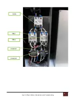
Page 44: ...Rev 3 Coffee Crafters Maintenance and Troubleshooting 44 Troubleshooting Figure 1 3 SSR 2 Contactor 1 Contactor 2 SSR 3 SSR 1 ...

Page 45: ...g 45 Note that the SSR s are installed with the writing upside down Potentiometer connections are on the top power connections are on the bottom Troubleshooting Figure 1 4 SSR Connections SSR 3 Motor Speed Control Module SSR 1 and 2 Heat Control Modules ...

Page 46: ...Rev 3 Coffee Crafters Maintenance and Troubleshooting 46 Troubleshooting Figure 1 5 Contactors Noark Contactors ...

Page 47: ...Rev 3 Crafters Wiring Diagram 47 Wiring Diagram Europe UK NZ Australia ...

Page 48: ...Rev 3 Crafters Wiring Diagram 48 Wiring Diagram America ...

Page 49: ...0 Roaster Rear Panel A9 RPK 1400 Roaster Lid A9 LID 1000 Heat Dam A9 RHD 1000 Electronic Bracket A9 REB 1000 Heat Chamber A9 HCA 1000 Heat Shroud Assembly A9 HAS 1000 Heat Element Mount Plate A9 EMP 1000 Air Box A9 AIR 1000 Blower Mount Bracket A9 BMB 1000 Chimney A9 RCW 1000 Distribution Block A9 RDB 1000 Distribution Block Cover A9 DBC 1000 Bottom Panel A9 RBP 1000 Foot Bracket A9 FB 1000 Bean L...

Page 50: ...0 Transition Manifold A9 BLW 1200 Chaff Bags 200 Micron Chaff Bags CCM size 1 7x16 200 400 Micron CC 1 7x16 400 3 hose clamp CC 3 HC 4 hose clamp CC 4 HC 6 hose clamp CC 6 HC Flexible Hose CC Flex 4x20 Semi Rigid Duct 6 x8 CC Duct 6 x 8 Electrical Assembly CC UL Ele Asm AX eBase Model Breaker CC 1D15UM Digi Thermometer Complete CC MS6501 Thermometer Probe CC A9 TCP 1000 Fotek SSR25 VA 1 4 watt CC ...

Page 51: ...ontactor 40 amp 240 vlt CC Ex9CK30B20 Power Distribution Block CCE 63133 Single red switch Cherry CC TRG22F2BBRLN Speed Control Knob CC SPKnob Temperature Controller F CCE 4020 Temperature Controller C CCE 4021 Heat Element Cartridges 240V 21 21852 00 220V Euro 21 21852 03 ...

Reviews: