background image

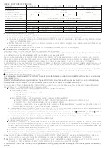
 ALARMS FOR SINGLE ASSEMBLY.

In case of simultaneous alarms, quit the automatic mode and go to manual mode, pressing  the pushbutton 

AUTOMATIC ON/OFF

 (led light 

PUMP will turn off). Using key


pq

will be displayed the succesive alarms. Once visualized, for leaving the menu,  press 

ENTER

 returning to 

MANUAL

 mode. 

A1 DRY RUNNING (   Failure verification    Final failure)

DESCRIPTION: i

f the system detects dry running during more than 10 seconds, it will stop the pump and the ART (Automatic ResetTest) will 

be activated. 
SYSTEM REACTION: after 5 minutes ART system will start again the pump during 30 seconds, trying to restore the system. In case of 
persistent lack of water, it will try it again every 30 minutes for 24 hours. If after all these cycles , the system still detects lack of water, pump 
will remain permanently out of order until the damage will be repaired.

SOLUTION: d

ry running,  it has been activated the safety system: you should verify the feeding of the hydraulic network. The pumps can be 

primed using the push-button START/STOP ( the led light AUTOMATIC should be off, if it is not, press the push-button to disable it).

Special case:

 if the pump cannot provide the programmed pressure (configuration mistake) the unit reacts as it was dry-running.

Special Case 2: 

this device manages the dry running control through the nominal current consumption of the pump. It must be 

verified  the introduced current consumption in the setup menu.

A2 OVER-INTENSITY(    Failure verification    Final failure)

DESCRIPTION: t

he  pump is protected against over currents by mean of the intensity values established in the installation menu. These over 

currents are produced generally by dysfunctions in the pump or in the electric supply.
SYSTEM REACTION: when detecting the thermal failure, the pump will be automatically stopped. The   system will try again to restart the   
pump when the demand of consumption require it. The control system will carry out 4 attempts in this circumstances. If the system remain 
locked after the 4th attempt, the  pump will remain definitively out of order.

SOLUTION: v

erify the state of the pump, for example the impeller could be blocked. Verify intensity values introduced in the configuration 

menu. Once the problem have been solved the operation will be restored  going to the “SET UP” menu ( see the chapter configuration) and 
configuring the adequated intensity values.

A3 DISCONNECTED P. (   Final failure)

DESCRIPTION: t

he Speedbox has an electronic safety system in case of no load detection.

SYSTEM REACTION: the device is disconnected..

SOLUTION: t

he wound of the motor and the pump consumption should be verified. Once the problem have been solved the operation will be 

restored  going to the "SET UP" menu (see the chapter configuration) and  introducing the  adequate intensity values. Verify the  fuses (see 
fig.3), in case of being melt  contact with technical service.

A5 TRANSDUCER (   Final failure)

DESCRIPTION: t

he transducer damages are showed in the  Speedbox LCD screen.

SYSTEM REACTION: the device operation is interrupted.

SOLUTION: 


check the external pressure transmitter.

A6 EXCESSIVE TEMP.    Final failure

DESCRIPTION: t

he system has a cooling device to keep the INVERTER  in optimum working conditions.  

SYSTEM REACTION: if an excessive temperature is reached the own system leaves the inverter out of service and as consequence the pump 
too.

SOLUTION: v

erify the temperature environment should be under 50 ºC.  Contact with technical service.

A7 SHORTCIRCUIT (   Final failure)

DESCRIP

TION: the Speedbox has an electronic system for protection against short circuits as well as peaks of current.

SYSTEM REACTION: the pump stops and then it starts again -performing  4 successive attempts. If the problem is not solved, the  pump will 
remain definitively out of order. 
SOLUTION: check the pump, if the problem persists, contact the technical service.

A8 OVERVOLTAGE -  A9 UNDERVOLTAGE (   Failure verification)

DESCRIPTION: the Speedbox has an electronic safety system against overvoltages and too low supply voltages.
SYSTEM REACTION: in case of overvoltage or undervoltage the system remains stopped until an adequate value of voltage is reached. In this 
case,  the system is automatically restored.
SOLUTION: check the electric supply.

ALARM INSTALLATION MASTER-SLAVE 

A10 COMUNICA 

(   Failure verification)

DESCRIPTION: If you have configured a Master-Slave system and communication cable is disconnected or there is a bad connection, the 
system stops. 
SYSTEM REACTION: The Master-Slave system stops and starts to operate individually. 
SOLUTION: Check the cable connection and if this is OK, check the connection inside the unit. Check the configuration of the Master-Slave 
system (setup menu). 

------
DESCRIPTION: blank screen.  
SOLUTION: check the electric supply. In case of being in right conditions,  the general fuse, located in the main plate (fig 1) should be verified.

-12-

Summary of Contents for 1006MT

Page 1: ...ON AND OPERATING INSTRUCTIONS INTRUKCJA MONTAŻU I OPERACJI INSTRUCTIONS POUR L INSTALLATION ET L EMPLOI INSTRUCCIONES PARA LA INSTALACIÓN Y UTILIZACIÓN EN PL FR ES 1006 MT 1010 MT 1106 MM 1112 MM 1305 TT 1309 TT ...

Page 2: ......

Page 3: ...e fabricación del producto El fabricante no se hará responsable de la garantía del producto en caso de una instalación o manipulación inadecuada Lea atentamente este manual para realizar la instalación del producto No deseche el manual después de haber realizado las operaciones de instalación puede ser útil para cualquier modificación de dicha instalación así como para solucionar cualquier problem...

Page 4: ...OMATIC mode When it is intermittent in MASTER SLAVE mode it means that this device will be auxiliary in the following cycle 7 ON OFF It allows to change from AUTOMATIC to MANUAL mode or vice versa 1 Pantalla LCD multifunción En situación de trabajo indica la presión 2 Pulsador MANUAL START STOP 3 Pulsador para entrar o salir de MENU 4 Pulsadores para aumentar o disminuir valores de programación qu...

Page 5: ...itar el golpe de ariete C It must be installed a pressure transmitter y otput 4 20 mA with pressure range either 0 10 bar or 0 16 bar Nalezy zamontowac czujnik cisnienia y wydajnosc4 20 mA z zakresem cisnienia 0 10 bar i0 16 bar installer un transmetteur de pression y avec 4 20 mA et la gamme de pression 0 10 bar ou 0 16 bar Se instalará un transmisor de presión y con salida 4 20 mA y rango de pre...

Page 6: ...ctor de presión Minimal level optional Minimalny poziom opcjonalnie Niveau minimal optionnel Sensor de nivel mínimo opcional Power supply Zasilanie Alimentazione elettrica Alimentación general Pump connection Połączenie pompy Connection pompe Conexión de la bomba 1106 MM 10 A 1112 MM 16 A 1006 MT 16 A 1010 MT 20 A General fuse Bezpiecznik ogólny Fusible général Fusible general Pressure transmitter...

Page 7: ...chematem 5 5 Przestawić złącza na obudowie Nakręć pokrywe i PG Jeśli urządzenia są wyposażone w kabel komunikacyjny reguluje on nastepujacy kod koloru 1 czarny 2 brazowy 3 szary 5 żółto niebieski Będą połączone według nastepujacych szczegółów A dwa przewody centralne brazowy i szary muszą być skrzyżowane ES Usar cables con aislamiento reforzado 1 Desatornillar la tapa y aflojar el PG pasacables si...

Page 8: ...mpy Connection pompe Conexión de la bomba Pressure transmitter Przetwornik ciśnienia Capteur de pression Transductor de presión Observe the polarity printed on the PCB Obserwuj polaryzację umieszczoną na PCB Respectez la polarité imprimé sur la carte Respetar la polaridad impresa en el circuito Connection master slave communication Połączenie komunikacyjne master slave Connexion communication mast...

Page 9: ...matem 5 5 Przestawić złącza na obudowie Nakręć pokrywe i PG Jeśli urządzenia są wyposażone w kabel komunikacyjny reguluje on nastepujacy kod koloru 1 czarny 2 brazowy 3 szary 5 żółto niebieski Będą połączone według nastepujacych szczegółów A dwa przewody centralne brazowy i szary muszą być skrzyżowane ES Usar cables con aislamiento reforzado 1 Desatornillar la tapa y aflojar el PG pasacables situa...

Page 10: ...ded with its own pressure transmitter MAIN CHARACTERISTICS n Wall mounted frequency inverter for the pump control n Control and safety system against over intensities n Control and safety system against dry operation n ART function Automatic Reset Test If the device has been stopped due to the action of the safety system against over current the ART tries to connect the pump with a programmed peri...

Page 11: ...20 240 V MM MT 400 V TT Dismount the cover of the electronic circuit and carry out the connections according to the indications located on the connection strip base n Do the power supply connection being sure there is a good earth connection L1 N MM MT L1 L2 L3 TT Do the connection by mean of magnetothermic switch in OFF mode n The earth conductor must be longer than the others It will be the firs...

Page 12: ...actory set Using pq we can change the values and press ENTER for validation Whenever we want to quit the configuration sequence press MENU After every ENTER it will appears automatically the different screens that constitute the configuration sequence MENU ENTER ENTER ENTER ENTER ENTER ENTER ENTER E X P E R T V X X Q O 1 9 Q 1 1 9 Q 2 8 A C C E L E R 1 0 F R E Q 8 K H z ENTER To start the configur...

Page 13: ...frequency value will be used as frequency stop in installations where the automatic detection of Speedbox do not act due to leaks in the system See hydraulic installation By mean of keys pq input the nominal current intensity value in A of the pump enabling the thermal protection This value is located over the characteristics plate of the motor Press ENTER for validation WARNING this value is link...

Page 14: ...nfiguration and configuring the adequated intensity values A3 DISCONNECTED P Final failure DESCRIPTION the Speedbox has an electronic safety system in case of no load detection SYSTEM REACTION the device is disconnected SOLUTION the wound of the motor and the pump consumption should be verified Once the problem have been solved the operation will be restored going to the SET UP menu see the chapte...

Page 15: ... restore attempts if it does not succeed the system is disabled To restore manually a device disabled by an alarm push AUTOMATIC ON OFF in MASTER device and then ENTER in the device with the alarm REGISTER OF OPERATION DATA AND ALARMS By using simultaneously MENU p during 3 is acceded to REGISTER OF OPERATION DATA AND ALARMS by mean of ENTER we can advance through the sequence once finished the se...

Page 16: ...ncji operacji SPEEDBOX konfigurowany jako MASTER rozpoczął pierwszy cykl jako główne urządzenie jeśli pompa jest pierwszym uruchomieniem w nastepnym cyklu staje sie wtórnym jeśli pompa jest drugim uruchomieniem i tak dalej W związku z tym że urządzenie jest skonfigurowane jako MASTER obejmuje kontrolę grupy ale ten fakt nie unika tej operacji na przemian jako urządzenie WTÓRNE Każdy SPEEDBOX musi ...

Page 17: ...309TT 1 mm vedi fig 4 n 2 1010MT 1 5 mm vedi fig 4 Jeśli konieczne jest zwiększenie długości kabla złacze zewnętrzne jest wykonywane zgodnie z wytycznymi dotyczącymi niskiego napięcia instalacji krajowej i rozmiaru sekcji kabla będzie według tych samych kryteriów n Sprawdź czy zasilacz jest 220 240V MM MT 400 V TT Zdemontować pokrywę obwodu elektrycznego i wykonać podłączenie zgodnie ze wskazówkam...

Page 18: ...razie watpliwosci skontaktuj sie z producentem Nacisnij ENTER MENU ZAAWANSOWANE Specjalna konfiguracja nie ma potrzeby dostosowywania tych wartości są fabrycznie ustawione Używając pq możemy zmieniać wartości i nacisnąc ENTER w celu zatwierdzenia Za każdym razem gdy chcemy zakończyć sekwencje konfiguracji naciskamy MENU Po każdym ENTER pojawią się różne ekrany które tworzą sekwencje konfiguracji M...

Page 19: ... intalacja hydrauliaczna Za pomocą pqwprowadź wartość znamionową silnika w A 0 10A Ta wartość jest umieszczona na tabliczce znamionowej silnika Poprzez ENTER zatwierdzamy UWAGA ta wartość jest powiązana z systemem alarmow bardzo ważne jest aby wprowadzić dokładne zużycie prądu wskazane na tabliczce znamionowej Za pomocą pq możemy wybrać język LANGUAGE ENGLISH LANGUE FRANÇAISE LINGUA ITALIANA IDIOM...

Page 20: ...ł konfiguracja i konfiguruj odpowiednie wartości intensywności A3 NIEPODŁĄCZONA POMPA OPIS SPEEDBOX posiada elektroniczny system bezpieczeństwa w przypadku braku wykrycia pompy REAKCJA SYSTEMU Urządzenie jest odłączone ROZWIĄZANIE Należy zweryfikować uszkodzenie silnika i zużycie pompy Po rozwiązaniu problemu operacja zostanie przywrócona przechodząc do menu SET UP patrz rozdział konfiguracji i wp...

Page 21: ...m wykona 4 próby przywrócenia jeśli uda się wyłączyć system Aby przywrócić ręcznie urządzenie wyłącz za pomocą przycisku alarmowego AUTOMATIC ON OFF i nacisnac ENTER REJESTR DANYCH OPERACYJYCH I ALARMÓW Używając równocześnie MENU p przez 3 sek jest rejestrowany REJESTR DANYCH oraz ALARMÓW za pomocą ENTER można przejść przez sekwencje po zakończeniu sekwencji powraca do głównego wyświetlacza Kolejn...

Page 22: ... control y protección de la bomba contra sobreintensidades n Sistema de protección contra el funcionamiento de las bomba en seco por falta de agua n Función ART Automatic Reset Test Cuando el dispositivo se encuentra parado por la intervención del sistema de protección por falta de agua el ART intenta con una periodicidad programada conectar el grupo por si se ha restablecido la alimentación de ag...

Page 23: ...006MT 1010MT 1106 MM 1305 TT 1309 TT 1 mm en función de la longitud del cable ver fig 4 n 2 1112MM 1 5 mm en función de la longitud del cable ver fig 4 Si es necesario incrementar la longitud de cable se realizará un empalme exterior siguiendo las directrices de los reglamentos de baja tensión aplicables al país de instalación y se dimensionará la sección de cable necesaria según este mismo criter...

Page 24: ...uencia de configuración pulsar MENU ENTER durante 3 VISUALIZACIÓN EN PANTALLA Con el dispositivo en modo automático LED AUTO ON mediante el cursor p se pueden visualizar los distintos parámetros de funcionamiento Donde n P es la presión de consigna en bar n P es la lectura de presión instantánea en bar n Hz es la frecuencia de giro del motor en Hz n A es la corriente instantánea consumida en A n º...

Page 25: ...fugas en la instalación Ver instalación hidraulica Mediante pq introducir el valor de intensidad nominal en A de la bomba para habilitar la protección térmica 0 10 A Este valor está reflejado en la placa de características del motor de la bomba Pulsar ENTER para validar ATENCIÓN este parámetro está relacionado con la detección de falta de agua es importante introducir el valor exacto indicado en l...

Page 26: ...mba se deberá ir al menu CONFIGURACIÓN e introducir los valores de intensidad adecuados A3 DESCONEX BOMBA Fallo definitivo DESCRIPCIÓN el Speedbox dispone de un sistema electrónico de protección en caso de no detectar una carga conectada RESPUESTA DEL SISTEMA desconexión del dispositivo SOLUCIÓN comprobar bobinado del motor y verificar el consumo de la bomba Una vez solucionado el problema de dich...

Page 27: ...ado por una alarma se pulsará AUTOMATIC ON OFF en el MASTER y luego ENTER en el dispositivo afectado REGISTRO DE FUNCIONES Y ALARMAS Pulsando simultáneamente las teclas MENU p durante 3 se accede al registro de funciones y alarmas se avanza en el registro mediante el pulsador ENTER al finalizar el último registro se vuelve al menú principal pulsando nuevamente ENTER La secuencia de visualización e...

Page 28: ...marche mais dans le cycle suivant se convertit en auxiliaire sa pompe est la deuxième à mettre en marche et ainsi successivement Par conséquent le fait qu un dispositif est configuré comme MASTER implique le contrôle du groupe mais n empêche pas qu il fonctionne alternativement comme dispositif auxiliaire Chaque appareil est fourni avec son transmetteur de pression CARACTÉRISTIQUES GÉNÉRALES n Mon...

Page 29: ... voir fig 4 n 2 1006MT 1010MT 1106 MM 1305TT 1309TT min 1 mm en fonction de la longueur du câble voir fig 4 n 2 1112MM min 1 5 mm en fonction de la longueur du câble voir fig 4 Si nécessaire augmentation de la longueur du câble de liaison extérieure est réalisée en suivant les lignes directrices de la réglementation basse tension applicables dans le pays d installation n Vérifiez que la tension de...

Page 30: ...ernier moment MENU ENTER ENTER ENTER ENTER ENTER ENTER ENTER E X P E R T V X X Q O 1 9 Q 1 1 9 Q 2 8 A C C E L E R 1 0 F R E Q 8 K H z ENTER VISUALITATION DE L ECRAN Avec l appareil en mode automatique LED AUTO ON en appuyant p sur on voit une succession de différents modes de fonctionnement n P est la pression de consigne bar n P est la pression instantanée bar n Hz est la fréquence de rotation d...

Page 31: ...intensité nominale en A de la pompe pour habiliter la protection thermique 0 10 A Cette valeur est indiquée sur la plaque de caractéristiques du moteur de la pompe Apoyeur aur la touche ENTER pour valider ATTENTION Ce paramètre est relié à la détection du manque d eau il est important d entrer la valeur exacte indiquée sur la plaque des caractéristiques Avec les touches pq on pourra choisir les la...

Page 32: ...tive DESCRIPTION électronique de détection de la consommation instantanée de la pompe si la le Speedbox dispose d un système consommation nést pas détecté c est quie la pompe est arrêtée REPONSE DEL SYSTEME Débranchement du dispositif SOLUTION Vérifier le bobinage du moteur et la consommation de la pompe Une fois solutionnés les problèmes de la pompe pour rétablir son fonctionnement il faudra alle...

Page 33: ...matique en cliquant sur AUTOMATIC ON OFF au dispositif MASTER puis poussez sur ENTER au dispositif avec l alarme REGISTRE DES DONNÉES OPÉRATIONNELLES ET DES ALARMES Appuyer même temps les touches MENU p pendant 3 pour accéder au registre des données operationnelles et des alarmes avec ENTER nous pouvons avancer par la séquence quand cette séquence est finie nous trouverons un autre fois l écran pr...

Page 34: ...gnetic Compatibility 2002 95 CE RoHS Directive Product s name Type SPEEDBOX 1006MT 1010MT 1106MM 1112MM 1305TT 1309TT As per the European Standards UNE EN 60730 1 1998 A11 1998 A2 1998 A14 1998 A15 1998 A16 1998 A17 2001 ERRATUM A1 2001 A18 2003 UNE EN 60730 2 6 1997 A1 1998 A2 1999 CORR A1 2001 CORR A2 01 EN 61800 3 2004 Adjustable speed electrical power drive systems Part 3 DÉCLARATION CE DE CON...

Page 35: ......

Page 36: ...arte w tej instrukcji Symboles d avertissement contenus dans le présent chapitre Símbolos de advertencia contenidos en este manual Risk by electric shock Risque de choc électrique Ryzyko dla ludzi i lub obiektów Rischio per le persone e o per gli oggetti Risque pour les objets et ou de gens Ryzyko porażenia prądem Riesgo por energía eléctrica Riesgo para personas y o objetos 130645D_12_2016 ...

Reviews: