background image

4

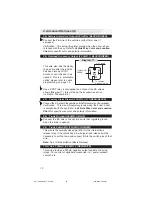
Refer to Diagram 2 to connect to the vehicle’s drivers unlock wire.

Type 2: Positive 5-Wire Door Lock System

Polarity fuse = Positive (+)

Single-Stage Unlock

Two-Stage Unlock

Connect wires 2/B, 1/A as shown in Diagram 3 (above).

Use a SPDT relay  ( Not Supplied)  and connect the 24/B wire to the
vehicle’s unlock wire as shown in Diagram 4 (below).

Connect wires 14/B, 3/A as shown in Diagram 2 (above).

1. Basic Harness (B),

 cont’d

X

Cut

From driver’s
Door Unlock Relay only

To driver’s
Door Motor only

3/A

Unlock

Switch

14/B
Unlock Motor

Diagram 2

Wires from control module

LOCK

UNLOCK

Unlock Motor 14/B

Unlock Switch 3/A

Lock Motor 2/B

Lock Switch 1/A

Vehicle Master Switch

To Door Lock Motors

Diagram 3

86

87

85

30

87a

X

24/B

Fused +12v

From Door Unlock
Switch or Relay

To Door Unlock
Motor

Diagram 4

CA-130 install rev 7-04.pmd

7/28/2004, 3:32 PM

4

Summary of Contents for CA-130

Page 1: ...g keys in vehicle during installation FCC COMPLIANCE This device complies with Part 15 of the FCC rules and with RSS 210 of Industry Canada Operation is subject to the following two conditions 1 This device may not cause harmful interference and 2 This device must accept any interference received including any interference that may cause undesired operation Warning Changes or modifications not exp...

Page 2: ...RED 16 Unused 16 SirenDrive 1Amp BLACK 17 Disarm OverrideButton Ground PLUGIN 18 Disarm OverrideButtonInput PLUGIN 19 HoodPinInput GRAY 20 DoorTriggerInput GRN VT 21 HornRelayDrive 500ma BRN BLK 22 LED2 Red PLUGIN 23 LED1 Black PLUGIN 24 SecondDoorUnlock 500ma BLU GRN System Layout System Layout CA 130M A Advanced Harness B Basic Harness C Unused Note The wire connection sections will identify eac...

Page 3: ...gative 2 B Lock Motor Wire 16 AWG BLUE 1 A Lock Switch Wire 87A 16 AWG BLUE BLACK 14 B Unlock Motor Wire 16 AWG GREEN 3 A Unlock Switch Wire 87A 16AWG GREEN BLACK 24 B Second Door Unlock 500mA 16 AWG BLUE GREEN IMPORTANT After installation set the polarity of this circuit by moving the fuse inside of the control module to positive or negative Type 1 Positive 3 wire door lock system Polarity Fuse P...

Page 4: ... in Diagram 4 below Connect wires 14 B 3 A as shown in Diagram 2 above 1 Basic Harness B cont d X Cut From driver s Door Unlock Relay only To driver s Door Motor only 3 A Unlock Switch 14 B Unlock Motor Diagram 2 Wires from control module LOCK UNLOCK Unlock Motor 14 B Unlock Switch 3 A Lock Motor 2 B Lock Switch 1 A Vehicle Master Switch To Door Lock Motors Diagram 3 86 87 85 30 87a X 24 B Fused 1...

Page 5: ...agram 5 to connect to the vehicle s driver s unlock wire Type 4 Vacuum Door Lock System Polarity Fuse Positive Note Two stage unlock will not work with this type of system 1 Basic Harness B cont d X 86 87 85 30 87a Cut Here From Driver s Door Only Unlock Switch or Relay Fused 12v Diagram 5 To Driver s Door Unlock Motor 14 B Fused 12v 2 B Lock Motor 3 A Unlock Switch 14 B Unlock Motor Master Vehicl...

Page 6: ...y Single Stage Unlock Two Stage Unlock Connect the 2 B wire as shown in Diagram 7 above Connect the 24 B wire as shown in Diagram 8 below Connect the 14 B wire as shown in Diagram 9 below 1 Basic Harness B cont d MODULE WIRES TO DOOR LOCK MODULE 2 B Lock 14 B Unlock Master Vehicle Door Lock Switch or Plunger Diagram 7 86 87 85 30 87a X 14 B Ground for positive polarity system 12v fused for negativ...

Page 7: ...the 5B wire with any other vehicle components 6 B Starter Input Key Side 14 AWG VIOLET RED 8 B Starter Output Motor Side 14 AWG VIOLET Locate the vehicle starter wire Verification This wire registers voltage only when the key is turned to the START position Cut the vehicle starter wire in half Verification after starter wire is cut KEY SIDE of starter wire registers voltage when the key is turned ...

Page 8: ... IMPORTANT After installation set the polarity of this circuit by moving the fuse inside of the control module to positive or negative 15 B 16 B Siren Installation 20 AWG If you are installing a siren Mount siren with bell housing facing down Use at least two 2 screws to secure siren to mounting location Connect siren BLACK wire to 16 B BLACK Siren Drive Connect siren RED wire to a 15 B RED siren ...

Page 9: ...ER TO ACCESS THE PROGRAMMING MODE CHANGE OPTION BANK 5 FEATURE 1 TO POSITIVE POLARITY PAGE 16 21 B Horn Relay Drive 500mA 20 AWG BROWN BLACK Locate the vehicle horn wire Verification This wire will register either positive or ground when the horn is pressed Connect the 21 B wire to the vehicle horn wire if the system is negative If the system is positive use a SPDT Relay not supplied and connect t...

Page 10: ...t the 4 A wire to the vehicle anti theft disarm wire if equipped Verification This wire will register ground when the driver s door is unlocked with the key Refer to Vehicle Wire Color and Location Chart for specific wire color and polarity information 8 A Trunk Pin Input 20 AWG BLUE Connect the 8 A wire to the vehicle s wire that registers ground when the trunk is opened 9 A Trunk Switch 87A 20 A...

Page 11: ... Input 20 AWG BLACK This wire is a ground input for an external sensor Connect this wire to the negative output of the external sensor L 2 Advanced Harness A cont d 11A Headlight wire 12v fused Diagram 11 5 86 87 85 30 87a To vehicle headlight If the wire in the vehicle tests positive use a SPDT relay not Supplied and connect as diagram 11 5 as shown 11A Aux 2 Headlight Output 500ma 20 AWG BLUE WH...

Page 12: ...smitters Program two transmitters three 3 times and the remaining transmitter twice 1 Open the driver s door 1 a The 20 B wire must initially see a ground to access programming 2 Turn vehicle ignition on 3 Press and hold emergency override button After 10 seconds the siren or horn will sound three 3 times This indicates that the unit has entered the transmitter programming mode 4 Release the butto...

Page 13: ... the dashboard indicates whether an option is on or off If the selected option is ON the indicator will light If the selected option is OFF the indicator will turn off The status indicator will turn on or off when an option is changed 5 When changes are complete press and release the emergency override button to continue to the next option bank Siren or horn will sound five 5 times 6 To reset all ...

Page 14: ...nsitivity Adjusting Full Shock Sensitivity 1 To program the sensitivity of the full trigger simply enter into option bank 1 then advance to Full Shock Adjustment feature 2 Once in the Full Shock Adjustment option use the LOCK button of the transmitter to increase and the UNLOCK button to decrease sensitivity 2 To verify the sensitivity strike the vehicle while in programming with the amount of for...

Page 15: ... latched 2 Pushand hold ON 1 OFF 2 5 NoiseControl Alarmwill 1 sound forfive30 sec cycles ON 1 OFF 2 Option Bank Three 6 Chirps Keyless Options 1 Ford SlamLock Option Delays doorlock time for Ford unlockdisable ON OFF 2 DoublePulseUnlock Unit Provides 2 pulses when unlocked ON OFF 3 IgnitionTriggeredLock Doorslock when alldoors are closedand ON OFF ignitionisturnedon 4 IgnitionTriggeredUnlock Doors...

Page 16: ...m 0 0 5 8 n i M 5 3 c e S 5 9 n i M 0 1 4 c e S 0 1 0 1 n i M 0 2 5 c e S 0 2 1 1 n i M 0 6 6 c e S 0 3 2 1 d e h c t a L Auxilary Adjustment Table 1 1 Fuse Size Location Trunk Output Dome Light Parking Lights Door Locks Heater 1 Heater 2 Ignition 1 2 Main Power 15A 15A 15A 25A _ _ _ _ 25A 25A 25A 5A 15A 15A 15A 20A 5A CA 130 install rev 7 04 pmd 7 28 2004 3 32 PM 16 ...

Page 17: ...system to chirp twice Next push twice then push and hold for digit 3 wait for system to chirp 3 times etc 3 Once all 4 digits are entered to your satisfaction either advance back to the first installer option if necessary or exit programming If at any time during the code entry process you decide to exit the process the system will default back to its previously learned code or the factory default...

Page 18: ... last 2 transmitters that are learned into the sytem will act as transmitter 1 2 i e program 3 tranmitters into system The 2nd from last transmitter will activate aux4 The last transmitter learned will activate aux 3 C Remote Transmitter Programming Personalized Transmitters 1 Open the driver s door 1 a The 20 B wire must initially see a ground to access programming 2 Turn vehicle ignition on 3 Pr...

Page 19: ...ess of LOCK button once if system is in pre arm mode Press LOCK then press FIND PANIC within 2 seconds to DISABLE the IT sTM Two quick chirps verify this function Pressing LOCK will re enable shock Pre arm mode 1 The unit will wait for the open door hood or trunk to be closed The LED is solid during pre arm 2 If the entrance is secured the siren horn will sound again parking lights will flash once...

Page 20: ...te which input triggered the alarm Number of Chirps 1 Interior Theft Sensor 2 Door input 3 Hood Input 4 Trunk input External Sensor 5 Ignition If Passive Arm option is set to On System will arm 60 seconds after key is turned off Press UNLOCK 1 Doors unlock 2 Factory alarm if equipped is turned off 3 Siren sounds once parking lights flash once 4 Courtesy lights turn on for 60 seconds or until ARM i...

Page 21: ...re closed and key is turned to ON position If Ignition Unlock option is set to On Doors unlock when ignition is turned off VALET MODE Press LOCK and UNLOCK simultaneously with vehicle ignition On System enters Valet mode LED double blinks Press LOCK and UNLOCK simultaneously with vehicle ignition On System exits Valet mode LED turns off CA 130 install rev 7 04 pmd 7 28 2004 3 32 PM 21 ...

Page 22: ...ul not to pinch the antenna under vehicle panels or route near moving parts 3 Route the antenna across the headliner to a position behind the rearview mirror 4 Attach the antenna to the inside of the windshield behind the rearview mirror The glass surface must be clean before mounting antenna Use rubbing alcohol to thoroughly clean the mounting location Remove protective backing and press firmly a...

Page 23: ...23 CA 130 install rev 7 04 pmd 7 28 2004 3 32 PM 23 ...

Page 24: ...24 CA 130 install rev 7 04 pmd 7 28 2004 3 32 PM 24 ...

Reviews: