Cobham Public
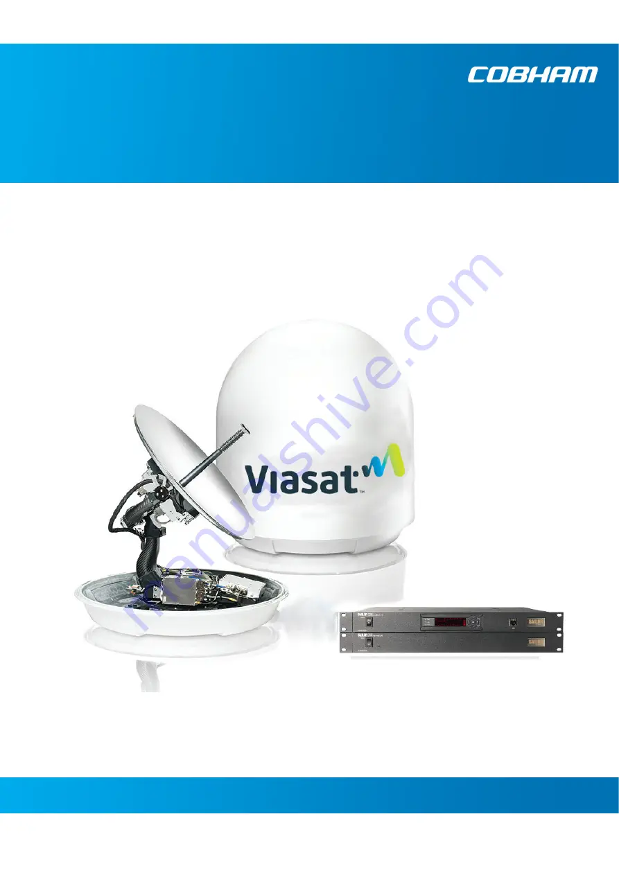
SAILOR 600 Viasat Ka
Installation and operation manual
Page 1: ...Cobham Public SAILOR 600 Viasat Ka Installation and operation manual ...
Page 2: ...atically into tracking mode It is preconfigured from the factory with a modem profile and a satellite profile 7 Verify that the SAILOR 600 Viasat Ka acquires the satellite Check that the ACU display shows ACQUISITION 8 Verify that the system is operational Check that the status in the ACU display shows TRACKING 98 166784 A Configuration task What to do and where to find more information Heading in...
Page 3: ...SAILOR 600 Viasat Ka Installation and operation manual Document number 98 166784 A Release date 8 November 2019 ...
Page 4: ...ne Thrane A S Lundtoftegaardsvej 93 D DK 2800 Kgs Lyngby Denmark Copyright 2019 Thrane Thrane A S All rights reserved Trademark acknowledgements Some product and company names mentioned in this manual may be trademarks or trade names of their respective owners GPL notification The software included in this product contains copyrighted software that is licensed under the GPL LGPL The verbatim licen...
Page 5: ...the ACU or the PIU is not allowed Only a technician authorized by Cobham SATCOM may perform service failure to comply with this rule will void the warranty Access to the interior of the Above Deck Unit is allowed Replacement of certain modules and general service may only be performed by a technician authorized by Cobham SATCOM Grounding cables and connections To minimize shock hazard and to prote...
Page 6: ...personnel Do not replace components with the power cable connected Under certain conditions dangerous voltages may exist even with the power cable removed To avoid injuries always disconnect power and discharge circuits before touching them Failure to comply with the rules above will void the warranty After installation make this manual available to the user for further reference ...
Page 7: ...98 166784 A v Record of Revisions Rev Description Release Date Initials A Original document November 2019 UFO ...
Page 8: ...vi 98 166784 A ...
Page 9: ...Installation of the ACU 3 22 3 5 Installation of the PIU 3 23 3 6 To connect the ADU ACU and PIU 3 24 Chapter 4 Interfaces 4 1 Interfaces of the ACU 4 1 4 2 Interfaces of the PIU 4 5 Chapter 5 Power and start up 5 1 Power up procedure 5 1 Chapter 6 Configuration 6 1 Introduction to the built in web interface 6 1 6 2 Heading input and position system 6 8 6 3 Calibration 6 10 6 4 Configuration with ...
Page 10: ...ons A 1 SAILOR 600 Viasat Ka system components A 1 A 2 Outline drawings A 4 Appendix B Ground and RF protection B 1 Why is a ground connection required B 1 B 2 Recommendations B 2 B 3 Alternative ground for steel hulls B 4 B 4 Alternative ground for aluminum hulls B 6 B 5 Alternative ground for fibre glass hulls B 7 B 6 Separate ground cable B 8 B 7 RF interference B 10 B 8 Jumper cable for ground...
Page 11: ...s Additional publications and information including most updated user guides white papers application notes release notes software updates training schedules and other technical information may be found on the ViaSat website located at maritime viasat com 1 2 Manual overview This manual has the following chapters Introduction Installation Interfaces Power and start up Configuration Installation ch...
Page 12: ... A Caution is an operation or maintenance procedure that if not obeyed can cause damage to the equipment Note A Note gives information to help the reader Important A text marked Important gives information that is important to the user e g to make the system work properly This text does not concern damage on equipment or personal safety All personnel who operate equipment or do maintenance as spec...
Page 13: ...d maritime VSAT antenna system operating in the following Ka band Uplink 27 5 30 GHz Downlink 17 7 20 2 GHz The system provides a high throughput full duplex IP data connections both on Viasat s quasi global Ka band satellite networks The following figure shows the current and anticipated coverage maps of the Ka service as of this manual s publication date For the latest information refer to marit...
Page 14: ...able to provide the Above Deck Unit ADU with both DC power data and control information The radome does not have to be removed neither before nor after the installation To protect the ADU the built in motors act as brakes during transport and when the ADU is not powered You can access the SAILOR 600 Viasat Ka remotely and make in depth performance analysis using the built in web interface The foll...
Page 15: ...n Secure connection HTTPS ACU and PIU and SSH ACU only Remote or local simultaneous software update of the ADU and ACU using a PC and Internet browser Full remote control and troubleshooting with built in test equipment BITE ACU with LAN NMEA 0183 RS 232 and RS 422 No scheduled maintenance Figure 2 3 ADU PIU and ACU Above Deck Unit ADU Antenna Control Unit ACU pTRIA Interface Unit PIU ...
Page 16: ...nfiguration It is stabilized by heavy duty vibration dampers in 3 axis and can be used in environments with elevations of 28 to 120 The ADU weighs 38 kg and is powered by the ACU The ADU is protected by a radome All communication between the ADU and the ACU passes through the a single standard 50 Ohm cable with N connector through the rotary joint No cable work is required inside the radome Figure...
Page 17: ...Modules in the SAILOR 600 Viasat Ka ADU 1 GNSS module 2 Cross elevation motor and encoder 3 Fan 4 Elevation motor and encoder 5 Inertial Sensor Module ISM 6 Integrated transceiver pTRIA 7 Polarisation Motor Module PMM 8 Pedestal Control Module PCM Figure 2 5 Above Deck Unit modules 1 2 ...
Page 18: ...s are automatically loaded on to the ADU via the ACU The system configuration is saved in two modules there is no loss of data at repair transmission All modules either have a service and power LED status indicator or support diagnostics via the web interface Each module is encapsulated in a metal box with self contained mounting bolts If necessary belts and modules can be exchanged on site Softwa...
Page 19: ...son Activated Self Test Continuous Monitoring CM is also available BITE error codes can be read out in the web interface and in the display of the ACU You can access the ACU web interface by navigating to the Antenna page in the main web interface ACU interfaces The ACU SAILOR 7016C has one LAN connector at the front disabled and the following interfaces at the rear panel N connector for PIU cable...
Page 20: ...art using the SAILOR 600 Viasat Ka you need to activate the system for the Viasat Ka service Contact your service provider for activation or visit the Viasat Maritime website www maritime viasat com 2 2 Part numbers and options The following model and part numbers are available for the SAILOR 600 Viasat Ka system The following options are available for the SAILOR 600 Viasat Ka system Figure 2 9 Co...
Page 21: ...ackage with bolts and washers Lifting harness SAILOR 7016C ACU Accessory kit for SAILOR 7016C ACU NMEA multi connector RJ45 patch cable 0 5 m RJ45 patch cable 2 m Power cable 1x230 VAC SAILOR 7024A PIU Accessory kit for SAILOR 7024A Coax cable N N ACU to PIU RJ45 patch cable 0 35 m Power cable 1x115 VAC 3 1 2 Initial inspection Inspect the shipping cartons immediately upon receipt for evidence of ...
Page 22: ...ector at the ADU PC and Internet browser Crimping tools 3 1 4 Transport of the antenna During transport the antenna must be able to move freely inside the radome You must follow the instructions below to keep a valid warranty WARNING To avoid electric shock do not apply power to the system if there is any sign of shipping damage to any part of the front or rear panel or the outer cover Read the sa...
Page 23: ...ed Painting the radome may impact RF performance and may lead to over heating causing the antenna to go in safe mode switch off Cobham SATCOM recommends that the radome should NOT be painted Painting the radome will not void the general warranty regarding material and workmanship etc It is only the performance that cannot be guaranteed Modifying the radome or using another radome The SAILOR 600 Vi...
Page 24: ...t it is approximately 5 m in diameter at 100 m distance This beam expansion continues with increasing distance Any obstructions such as masts funnels bridge house etc within this field can cause signal degradation or signal loss For optimum performance adhere to the following guidelines 1 Place the ADU so that it has as much free line of sight as possible without any structures in the beam through...
Page 25: ...ch blocking zone is set up with azimuth start and stop and elevation angle The blocking zones are set up in the built in web interface of the ACU during configuration For further information see To set up blocking zones on page 6 16 Figure 3 2 2 blocking zones with no transmit zones azimuth example Figure 3 3 Blocking zone with no transmit zones elevation angle example Antenna 360 000 45 90 180 13...
Page 26: ...ied to the ADU The g force also depends on the roll period of the ship see Table 3 1 If the g force applied is too high performance and ADU signal stabilization may be reduced and eventually the ADU may be damaged See the following table for allowed mounting heights above the ship s motion centre Even though it is recommended to mount the ADU high keep the distance between the ADU and the ship s m...
Page 27: ... interface to the ship If it is necessary to use a tall mast you must stabilise the mast with bracing Note that the design values given below depend on rigid ADU to ship interfaces The cross sectional properties and the corresponding maximum free length give a natural frequency close to 30 Hz Shorten the mast length as much as possible to obtain higher frequencies Preferably mount stays or wires t...
Page 28: ...thickness is in the following design examples set to 5 mm and the brace wall thickness to 4 mm A larger wall thickness yields more stiffness valid design whereas a thinner wall thickness yields a weaker structure not valid design Figure 3 5 ADU mast flange top and side view measures in mm 200 2 0 0 200 2 0 0 min 5 min 5 min 80 350 20 2 As close as possible min 5 SCALE 3 10 DETAIL A Min four gusset...
Page 29: ...st diameter Example The mast outer diameter is 150 mm Then the mast length must be shorter than 82 cm Figure 3 7 Free mast length and example bracing for a tall mast Note Make sure that there is free space below the drain tube See also Condensation water intrusion and deposits on page 3 15 Free mast length Figure 3 8 Maximum mast length for a mast without braces ...
Page 30: ...e the more support they add to the mast The 30 40 degrees between the braces and the mast should be respected Figure 3 9 Mast with three braces measures in mm 30 40 b r a c e a s s h o r t a s p o s s i b l e s e e n o t e 120 120 120 variable brace connection point see graph variable mast length see graph variable diameter see graph min 4 variable diameter see graph evenly distributed applying mo...
Page 31: ... and the brace mast connection point is 56 cm from the top of the mast Make sure that the brace outer diameter is big enough for the selected mast length Example For a mast length of 250 cm the brace outer diameter must be minimum 65 mm Figure 3 10 Maximum mast length and connection point for a mast with three braces Figure 3 11 Minimum brace outer diameter 100 150 200 250 300 350 400 20 25 30 35 ...
Page 32: ...dar vary from ship to ship However it is possible to give a few guidelines 1 Since a radar radiates a fan beam with a horizontal beam width of a few degrees and a vertical beam width of up to 15 you can avoid the worst interference by mounting the ADU at a different level meaning that the ADU is installed minimum 15 above or below the radar antenna Due to near field effects the benefit of this ver...
Page 33: ...of the Ka band connection The degradation will be most significant at high radar pulse repetition rates As long as receiving conditions are favourable this limited degradation is not important However if receiving conditions are poor e g due to objects blocking the signal path heavy rainfall or icing low satellite elevation and violent ship movements the small extra degradation due to the radar s ...
Page 34: ...DU typically down to one meter outside the main beam L band antennas If L band antennas are installed on the same vessel keep a minimum distance of 3 meters from the SAILOR 600 Viasat Ka ADU to the L band antenna Other transmitters See the following figure for minimum recommended distance to transmitters in the frequency range below 1000 MHz CAUTION The ADU must never be installed closer to a rada...
Page 35: ...sible install the radome such that direct spray of seawater is avoided 2 Make sure the ADU s drain tube is open and that there it free space between the drain tube and the mounting surface so water can escape and there is ventilation for the ADU 3 Do not use pneumatic tools for cleaning the radome especially at a short distance and directly at the split between top and bottom 4 Do not place the AD...
Page 36: ... 3 12 Install the ADU at a location where vibrations are limited to a minimum 3 3 2 Overview The ADU is shipped fully assembled You have to install it on the mast and attach the ADU cable WARNING Use the already mounted lifting harness to lift the ADU without damaging the radome WARNING The ADU may be subject to swaying motions in windy conditions Always use tag lines to stabilise the ADU during h...
Page 37: ...obham SATCOM part number TT 48 149056 is designed tested and conforms to the requirements for lifting equipment in DIRECTIVE 2006 42 EC OF THE EUROPEAN PARLIAMENT AND OF THE COUNCIL of 17 May 2006 on machinery and amending Directive 95 16 EC recast The Working Load Limit WLL is defined as 40 kg The harness may only be used for lifting the ADU Figure 3 15 Use of the lifting harness and tag lines fo...
Page 38: ...s 20 dB at 1675 MHz This is to ensure optimum performance of the system Installation procedure To install the ADU do as follows 1 Install the mast with the mast flange and have the 4 M10 bolts ready 2 Open the ADU cardboard packaging 3 Remove the foam protection layer at the top 4 Take the 4 lifting straps and connect them to the crane hook Figure 3 16 ADU installation 4 lifting straps on crane ho...
Page 39: ...the ADU 8 Read carefully and follow instructions given in the next section on grounding 9 Remove the harness as shown in the following figure 10 Locate the quick link 1 and open it 2 11 Pull the strap with the quick link through the harness to remove it 3 12 Slide the harness over the top of the ADU 4 13 Dispose of the harness in a responsible manner 14 Attach the N connector of the ADU cable to t...
Page 40: ...que value 30 Nm 3 Seal the area suitably to avoid corrosion of the grounding point recommended For optimum grounding connect the ground wire to the bolt marked in the figure below If the ADU cannot or should not be electrically connected directly to the mounting surface you can use a separate grounding cable to make the connection between the ADU and the common ground to which the ACU is also conn...
Page 41: ...ve ADU cable make sure that the following requirements are fulfilled 1 Check the data sheet from the cable supplier to verify the values The RF attenuation and the DC resistance are below the maximum values specified below ADU cable RF attenuation at 1675 MHz Max 20 dB including connector ADU cable modem attenuation at 36 and 54 MHz Max 4 dB ADU cable loop DC resistance max 0 9 Ohm 2 Respect the s...
Page 42: ...f the ACU connectors For information about power source and power cable requirements see Power and start up on page 5 1 3 4 2 To ground the ACU To ground the ACU do as follows 1 Make sure that the grounding requirements are met See the appendix Ground and RF protection on page B 1 for details about grounding 2 Make sure that the rack is connected to ship ground 3 To ensure that the ACU is grounded...
Page 43: ...2 To ground the PIU To ground the PIU do as follows 1 Make sure that the grounding requirements are met See the appendix Ground and RF protection on page B 1 for details about grounding 2 You must ground the ADU cable coax cable with an N connector at both ends at the PIU end Use a short cable from the PIU to a grounding point in the rack and connect the short cable to the ADU cable at this ground...
Page 44: ...CU and the PIU 1 Connect LAN1 at the ACU to LAN1 at the PIU 2 Connect the antenna cable to the connector marked Antenna at the ACU and the connector marked ACU at the PIU 3 Connect a PC at the LAN2 interface of the PIU for access to the web interface for configuration or Internet user data Figure 3 22 Connection between ADU ACU and PIU 2 1 AC power PIU ACU 3 ...
Page 45: ... following figure shows the connector panel of the ACU 4 1 2 AC input connector Connect the power cable to the AC power connector Figure 4 1 ACU LEDs display and keypad detailed example Main NAV GH LAN 1 TRACKING SAT 009 0 E RX 1 TX MA Figure 4 2 ACU connector panel with AC power Tx In not used Rx Out not used Ground LAN 1 Connect to PIU LAN 2 3 4 Disabled RS 422 not used NMEA GPS heading input AC...
Page 46: ...d pin assignment Important Do not use TNC connectors on the ACU ADU antenna cable or on pigtails TNC connectors cannot carry the DC current for operating the ADU Outline on the ACU Pin number Pin function 1 Inner conductor 2 Outer conductor GND Shield Table 4 3 F connector Rx and Tx outline and pin assignment Outline on the ACU Pin Pin function Wire color 1 Not connected 2 NET H NMEA 2000 White 3 ...
Page 47: ...l pair Size No 24 AWG 0 24 sq mm or heavier Characteristic impedance 95 140 Ohm Propagation delay 5 nanoseconds per meter maximum 15 Twists minimum per meter 4 1 6 RS 232 and RS 422 connectors The ACU has an RS 232 and RS 422 connector The connectors are not used in normal operation 1 Hardware prepared for NMEA 2000 for future use NMEA 2000 power 9 16 VDC NMEA 2000 LEN Load Equivalency Number 2 10...
Page 48: ...le length per connection is 100 m The Ethernet cable type must be CAT5 shielded Outline on the ACU Pin Pin function 1 Ground 2 Line A RXD 3 Line B TXD 4 Ground 5 Ground 6 Not connected 7 Line A RXD 8 Line B TXD 9 Not connected Table 4 6 RS 422 connector male outline and pin assignment ACU 1 5 6 9 Outline Pin Pin function Wire color 1 Tx White orange 2 Tx Orange 3 Rx White green 4 Not connected Blu...
Page 49: ...e type 4 2 3 2 LAN connectors The PIU has 2 Ethernet connectors type RJ45 LAN 1 connects to the ACU on LAN port 1 LAN 2 is used to connect a user PC for configuration and Internet access The maximum cable length per connection is 100 m The Ethernet cable type must be CAT5 shielded For outline and pin allocation see table 4 7 on page 4 4 Figure 4 3 Connector panel of the PIU Outline on the PIU Pin ...
Page 50: ...ed for first time power up or receive data from the built in Viasat PIU when in normal operation The LEDs Power and Fail Pass are steady green the LED Logon is off For further information on status indicators see Status signalling with LEDs and status messages on page 8 11 Make sure there are no hardware failures or error codes shown in the display of the ACU For more information on error codes an...
Page 51: ...nitializing ADU SW upload If the software versions in the ADU and ACU are not the same a software update is done during startup ADU POST READY POINTING ANTENNA ACQUIRING SIGNAL TRACKING 5 1 2 SAILOR 600 Viasat Ka operational When the display shows TRACKING MDM NETOK and the LED Logon is steady green the system is operational Figure 5 1 ACU LEDs display and keypad detailed example Main NAV GH LAN 1...
Page 52: ... the Google Chrome or Firefox browsers state which will be supported Installation of software is not necessary Accessing the web interface is described below 6 1 2 Connecting to the terminal web interface To connect to the web interface of the terminal do as follows 1 Switch on the ACU 2 Wait until the LEDs on the front plate of the ACU show that the system is ready to be configured Power LED Gree...
Page 53: ...aunch the web browser Mozilla Firefox on the support PC 6 At the web browser s address entry field enter the modem s IP address i e https 192 168 100 1 and press Enter When the Home Page is displayed you have verified that the connection to the SAILOR 600 Viasat Ka can be established The web interface is ready for use The terminal web interface has the following tabs Antenna Modem Figure 6 1 Termi...
Page 54: ...is scanning or attempting to connect Syncing The modem is syncing with the network and antenna Synched The modem synched correctly Ranging Ranged The modem is configuring operating ranges Network Entry The modem is gaining access to the ACU DHCP The modem is configuring itself to connect with the network Online The modem is connected to the network and online Online Time Displays the duration of t...
Page 55: ...a Return Link connection several minute may pass before the icon changes color Green Indicates the modem has established a Return Link connection Network Third Icon Gray Indicates that there is no Link connection or the Network Entry is disabled several minute may pass before the icon changes color Yellow Indicates the modem is initiating a network connection several minute may pass before the ico...
Page 56: ...dBm Displays the modem s power level Rx SNR dB Displays the Signal to Noise Ratio PTRIA Comm Status Displays if the modem is collecting and transmitting data with the pTRIA Cable resistance dB Displays round trip resistance between the Modem and pTRIA Temperature C Displays the pTRIA s operation temperature Table 6 2 Items in the section General Item Description IP Address Displays the modem s IP ...
Page 57: ... displayed 5 To create or change the password select ADMINISTRATION User login and locate the section Change Login 6 Type in the new password minimum 8 characters and click Change No old password is required After 1 hour or a restart the new administrator password is required If you cannot establish a connection there might be problems with the Proxy server settings of your PC See Proxy server set...
Page 58: ...duction to the built in web interface 98 166784 A Chapter 6 Configuration 6 7 6666 Configuration For a detailed introduction to the web interface see Overview and dashboard on page 6 12 Figure 6 3 Dashboard ...
Page 59: ...erface SETTINGS Navigation example Heading input Description External Heading input from the vessel s gyro compass default If there is no heading input due to failure alarms are raised and the antenna continues in gyro free mode When heading input is available again and a new acquisition is made alarms are cleared See also Operation in gyro free mode on page 6 11 Fixed Use this setting for making ...
Page 60: ...sition for up to 10 seconds If RX lock is detected for more than 20 of the time the antenna goes to Tracking None Important You must make an azimuth with Fixed before you can use this setting This is required in order to be able to use blocking zones After a successful azimuth and cable calibration you must change the heading input setting from Fixed to None Select this setting after a successful ...
Page 61: ...ter finding the satellite the system can calculate the azimuth offset of the ADU installation Automatic azimuth calibration with an active satellite profile You can enable automatic azimuth calibration even if there is no line of sight to an azimuth calibration satellite the place of installation To be able to use this feature you must have made a valid satellite profile and activate it When the v...
Page 62: ...h direction of the satellite is not known In this case the antenna will start a 360 degrees sky scan and scan until it finds a satellite The search time to find the satellite and start tracking is therefore increased considerably If the ship is on a steady course and sails at a speed over ground above 5 kn the system can use an estimated heading from the current GPS position This will reduce the s...
Page 63: ...enus submenus and topics You can click on each menu in the site map to go directly to the page or display the respective submenu The Dashboard is the first screen that is displayed when the user or administrator enters the IP address of the web interface of the ACU and the user name and password The Dashboard is used for viewing properties and status of the ACU and ADU Figure 6 8 Topics in the ant...
Page 64: ...me is useful for identifying the system at remote login and when requesting reports from the system The host name is recommended to contain the name of the vessel To change the host name see To configure the LAN network on page 6 17 5 The contents section shows the page selected in the navigation pane This section is used for viewing or changing settings or for performing actions For a description...
Page 65: ...ce 2 of the PIU 2 Open your Internet browser and enter the IP address of the PIU Default IP address https 192 168 100 1 3 Select click the link to the ACU Status field in the icon bar The top bar shows the current status of the antenna Antenna initializing Antenna SW upload Antenna POST error XIM data error Unrecoverable XIM data error System upgrade Antenna POST pending Antenna POST Safe Mode err...
Page 66: ... Software version Part names serial numbers for ACU and ADU software version of the SAILOR 600 Viasat Ka Table 6 7 Web interface DASHBOARD first section MODEMa a Items shown in this list may vary they depend on the current modem Description Model Modem name RX locked status Terminal has acquired forward link signal TX allowed Yes Terminal is allowed to transmit No Terminal is not allowed to send d...
Page 67: ...le by clicking on Satellite profiles or Modem profiles 6 5 1 To set up blocking zones You can define blocking zones by entering azimuth and elevation angles for each blocking zone To enable a blocking zone you must select Active To define and set a blocking zone do as follows 1 Select SETTINGS Blocking zones 2 Select Active to enable the blocking zone Figure 6 10 Web interface SETTINGS Blocking zo...
Page 68: ...system To configure the LAN network go to SETTINGS Network Figure 6 11 Blocking zone example 315 45 degrees Figure 6 12 Blocking zone example 45 315 degrees Important You must enter 2 different elevation angles to have an active blocking zone 360 000 45 90 180 135 225 270 315 Antenna Blocking zone 315 45 360 000 45 90 180 135 225 270 315 Antenna Blocking zone 45 315 Important The SAILOR 600 Viasat...
Page 69: ...nd in reports The default host name is acu You can change the name Letters a z digits 0 9 and hyphen are allowed Note The host name must start with a letter LAN Port 1 This network is connected to the PIU LAN port 1 mode is always Static static IP address IP address and Netmask cannot be changed LAN Port 2 3 and 4 Disabled DNS setup Set the following DNS source Static Primary DNS 192 168 100 1 Sec...
Page 70: ... enable remote syslog default Off 3 Enter the IP address of the syslog server to which the syslog messages will be sent 4 Click Apply 6 5 4 Administration In this section of the web interface you can configure the following administrative settings To change the password and log out To import and export a system configuration To reset to factory default settings Gateway setup Set the following Defa...
Page 71: ...rd 2 Enter the new password minimum 8 characters and retype it on the next line 3 Click Change At the next logon the new password is required 4 Click Logout to log out of the web interface If you have not entered anything for 30 minutes you are logged off automatically If you have forgotten the administrator password do as follows 1 On the ACU keypad push and hold the left arrow key for 5 seconds ...
Page 72: ...ATION User login and locate the section Change Login 6 Type in the new password minimum 8 characters and click Change No old password is required After 1 hour or a restart the new administrator password is required 1 On the page ADMINISTRATION and User administration the administrator can change the password for the guest user To change the current guest password do as follows 1 Enter the new pass...
Page 73: ...STRATION Export import config 2 Click the button Export Follow the download instructions on the screen To load a configuration from a file do as follows 1 Select ADMINISTRATION Export import config 2 Click the button Browse and locate the configuration file cfg file you want to upload 3 Click the button Open 4 Click the button Upload To clone a system configuration do as follows 1 Reset to factory...
Page 74: ... SAFE MODE error followed by an error description READY waiting for data from the modem or no satellite profile selected POINTING ANTENNA locating the satellite ACQUIRING SIGNAL acquiring the satellite signal TRACKING tracks the current satellite AZIMUTH CALIBRATION TEST NOT READY waiting for input from GNSS e g GPS NOT READY INITIALIZING NOT READY NEED POS 2 Current menu see The menu tree on page...
Page 75: ... Not ok unknown Extern mute U u Modem TX m M ADU TX a A Tx pol X C L R After 1 hour the display is dimmed to lowest intensity Press any key to light up the display 6 6 2 Navigating the menus Use the keypad to navigate the menus Press OK or to select a menu item Use the arrow keys and to go through the menu items or enter a number digit by digit Use the arrow keys and to go through the settings and...
Page 76: ...ers position software version and serial numbers of the ADU and ACU MODEM Selected PIU type and setup including signal level NETWORK IP addresses and netmasks of the LAN connectors of the ACU and the management mask SATELLITE Current satellite information This information is selected using the web interface EVENTS System events Active events are shown as X ACTIVE EVENTS in the MAIN display Press O...
Page 77: ...ed modem type TX ENABLE On or off information delivered by the connected PIU RX LOCK On or off information delivered by the connected PIU SIGNAL LEVEL Table 6 13 MODEM menu of the ACU SATELLITE menu Description POSITION Position of the current satellite RX POLARISATION Not applicable TX POLARIZATION Not applicable RX FREQUENCY Ka band receiving frequency of the active satellite auto selected by mo...
Page 78: ...le the ACU and ADU do the following 1 Press and hold and until the ACU display shuts down and the ACU and ADU reboots 2 Wait until the system has rebooted and is operational again The last active satellite profile will be used EVENT menu Description EVENT In this menu all active events are listed Use and to go through the active events Events can be of the type WARNING or ERROR If a new event occu...
Page 79: ... installed the system you can test it to verify it is ready for customer delivery Follow the check lists below to test the system for proper operation Installation check list Antenna Installation check list ACU and PIU connectors and wiring Installation check list Functional test in harbor ...
Page 80: ...U radiation hazard on page 3 6 6 Check that the mounting height of the antenna is in accordance with the ship s min roll period See Ship motion and offset from the ship s motion centre on page 3 6 7 Make sure that the requirements for mast foundation and height including flatness gusset plates and distance from welding seams are met See ADU mast design Mast foundation and height on page 3 7 8 Make...
Page 81: ...na N connector is properly connected with the 50 Ohm RF cable Visual inspection of the bottom of the ADU 4 Check that the ACU and PIU N connectors are properly connected with the 50 Ohm RX cable Visual inspection of the connector panel of the ACU 5 Check that the ACU s NMEA 0183 connector is connected to the NMEA 0183 bus of the vessel using the included multi connector Visual inspection of the co...
Page 82: ...e PIU The PIU needs no separate setup See To connect the ADU ACU and PIU on page 3 24 3 Make sure that the computer has no access to the Internet through other means Wifi 3G 4G etc Open a command line window and type ping 4 2 2 2 Check that you get a response 4 Make sure that the computer has no access to the Internet through other means Wifi 3G 4G etc Open a web browser and browse to e g www goog...
Page 83: ... 8 This chapter has the following sections To get support Software update Status signalling with LEDs and status messages s Removal and replacement of the ACU Removal and replacement of ADU modules Troubleshooting basics To return units for repair ...
Page 84: ...ad the MIB file and reports To enter contact information and view legal notices 1 Select HELPDESK from the left navigation pane 2 Click the link to enter support contact information and click Apply 3 Click the link Legal notices to see the licence text for the source code of the parts of the SAILOR 600 Viasat Ka software that falls under free and open source software To download diagnostics and st...
Page 85: ...d ADU The temperature is measured every 5 minutes within an hour and is then averaged and incidents are logged in the diagnostic file System log You can download a statistics report This report contains information relevant for the service personnel during troubleshooting You can also configure the system to send statistics reports at defined time intervals To generate a report do as follows 1 Sel...
Page 86: ...ation and remedy see List of ADU events on page C 2 and List of ACU events on page C 7 You can clear the event history in the diagnostic report this will not change the configuration To clear the event history do as follows 1 Click Factory default in the ADMINISTRATION page 2 Click the button Clear event history Self test You can start a self test of the SAILOR 600 Viasat Ka ADU and ACU The self t...
Page 87: ...st be disabled before accessing the web interface Most browsers support disabling of the Proxy server settings for one specific IP address so you can disable Proxy server settings for the web interface only if you wish Consult your browser help for information To disable the use of a Proxy server completely do as follows 1 In Microsoft Internet Explorer select Tools Internet Options Connections LA...
Page 88: ...ce 98 166784 A 2 Clear the box labelled Use a proxy server for your LAN 3 Click OK When the proxy server settings are disabled close and restart your browser You may need to change this setting back on return to your Internet connection ...
Page 89: ...play brightness setting To reset to factory default settings do as follows 1 Click the menu item ADMINISTRATION Factory default 2 Click Reset to factory default 3 Click Clear event history to clear all registered events 4 Click Reset Modem Important A reset to factory default will delete all settings including satellite and VSAT modem profiles blocking zones network setup user permissions and ACU ...
Page 90: ...ch on the ACU Wait until the ACU has finished initializing 2 Connect a PC to LAN2 of the PIU 3 Open your Internet browser and enter the IP address The IP address of the PIU is http 192 168 100 1 4 Type in the user name admin and the administrator password to access the web interface 5 Click on the link to the ACU 6 Click the menu item SERVICE The UPLOAD page is displayed 7 Click Browse and locate ...
Page 91: ...MODE in the top left corner 4 Release the arrow keys and 5 Connect a PC to LAN port 3 of the ACU 6 Set the IP address of the PC to static IP 192 168 0 2 Subnet 255 255 255 0 7 Open an Internet browser and type http 192 168 0 1 Default IP address of the ACU 8 Click Browse and locate the software file 9 Click Upload The upload procedure takes a couple of minutes When done the ACU automatically resta...
Page 92: ...een Pass Fail LED on the front of the ACU must become steadily green To verify the software update do as follows 1 Verify that the Pass Fail LED is not red nor flashing orange once every 2 seconds 2 Wait until the Pass Fail LED is green 3 Verify that the software update has been completed successfully You find the software version number in the DASHBOARD window of the web interface Figure 8 7 Veri...
Page 93: ...ethods for signalling the system status LEDs on the front panel of the ACU are used to signal Power on off Logon Fail Pass The built in web interface of the ACU shows any events BITE error codes with a short message describing each error This is also displayed in the ACU In an error situation one of the following system status messages may be shown ACU POST error ADU POST error SAFE MODE plus info...
Page 94: ...ower supply failure Off No power Logon Flashing green Current status is displayed Searching satellite Identifying satellite Carrier lock TX enabled from modem Steady green Satellite link established Off No satellite link acquired Fail Pass LED Steady red A fault which prevents operation is present in the system ACU ADU MODEM Flashing green A Power On Self Test POST or Person Activated Self Test PA...
Page 95: ...a Cobham SATCOM service partner The figure below shows the modules and their position Some modules are equipped with LEDs for status information and troubleshooting 1 GNSS module 2 Cross elevation motor and encoder 3 Fan 4 Elevation motor and encoder 5 Inertial Sensor Module ISM 6 Integrated transceiver pTRIA 7 Polarisation Motor Module PMM Figure 8 8 Above Deck Unit modules 1 2 ...
Page 96: ...A Interface Module PIM 10 Rotary joint 11 Zero Reference Module ZRM 12 Feed horn 13 Field Vector Driver Module FDM Before contacting your service partner check the LEDs on all modules PCM PMM and ISM See LEDs of the ADU modules on page 8 11 and LEDs in the ACU on page 8 12 Figure 8 9 Above Deck Unit modules 2 2 ...
Page 97: ...ent messages overview on page H 1 8 6 2 Event list for troubleshooting You can use the event list for troubleshooting For more information on the event list see Options for support on page 8 2 You can download the event list as part of a diagnostics report 8 6 3 Diagnostics report for troubleshooting You can generate a diagnostics report containing results from the POST all events and system log i...
Page 98: ...To return units for repair 8 16 Chapter 8 Service 98 166784 A ...
Page 99: ...A AAAA Technical specifications Technical specifications A This appendix has the following sections SAILOR 600 Viasat Ka system components Outline drawings A 1 SAILOR 600 Viasat Ka system components A 1 1 General specifications ...
Page 100: ...al Sine EN60945 8 7 2 DNV A MIL STD 167 1 5 1 3 3 5 Random Maritime Vibration survival Sine EN60945 8 7 2 dwell MIL STD 167 1 5 1 3 3 5 dwell EN60721 3 6 class 6M3 mod by EN60721 4 6 Shock EN60721 3 6 class 6M3 mod by EN60721 4 6 Temperature ambient Operational 25 C to 55 C Storage 40 C to 85 C ANTENNA CABLE PIU to ADU cable Single 50 coax for MoCA modem and power ABOVE DECK UNIT ADU Antenna type ...
Page 101: ...D BRAKABLE DAMPABLE PART AND A METHOD FOR BRAKING A MOVABLE PART AN ASSEMBLY COMPRISING A MOVABLE AND BRAKABLE DAMPABLE PART AND A METHOD FOR BRAKING A MOVABLE PART PCT EP2014 057527 20414PCT00 PCT EP2015 064100 A VEHICLE VESSEL AIRPLANE WITH A ROTATABLE ANTENNA CN 104641507 A 2873113 US 2015 0200701 A1 10 2015 7003879 Combined antennas without switch Combined antennas without switch Combined ante...
Page 102: ... Sheet 1 of 1 Telecommunications Engineering Copenhagen Denmark A1 NEXT ASSY USED ON APPLICATION UNLESS OTHERWISE SPECIFIED DIMENSIONS ARE IN MILLIME TRES AND TOLERANCES ARE IN ACCORDANCE WITH DS ISO 2768 1 F 1 2 3 4 1 2 3 4 D C B A D C B A 99 121451 Rev A 110 907 200 18 74 200 220 226 818 A 01 Original 20170822 TOB 20170822 20170822 20170822 OUTLINE DRAWING SAILOR 60GX 600Ka 600Ku TT94 156941 Sca...
Page 103: ...UNLESS OTHERWISE SPECIFIED DIMENSIONS ARE IN MILLIME TRES AND TOLERANCES ARE IN ACCORDANCE WITH DS ISO 2768 1 F 1 2 3 4 1 2 3 4 D C B A D C B A 99 121451 Rev A B B B B 425 2 0 8 319 3 0 5 482 6 0 5 43 65 0 3 31 75 0 3 461 67 0 3 3 4 3 4 5 95 0 1 A01 Original 16 02 29 AKJ A02 LAN connector on frontplate orientation flipped 18 09 10 SBW 16 02 29 16 02 29 16 02 29 yy mm dd OUTLINE DRAWING ACU 7016C T...
Page 104: ... TO COBHAM PLC AND SHOULD NOT BE USED WITHOUT WRITTEN PERMISSION 1 of 1 SHEET 1 2 SCALE FIRST ANGLE PROJECTION TT94 162062 A1 DRAWING NO ASSET NO SIZE Outline drawing for PIU 2019 08 15 Kenneth Petersson AP 2019 08 15 Tommy Olsen CH MATERIAL TITLE 2019 08 15 Kenneth Petersson DR UNLESS OTHERWISE SPECIFIED DIMENSIONS ARE IN MILLIMETERS AND TOLERANCES ARE IN ACCORDANCE WITH ISO 2768 m SURFACE TREATM...
Page 105: ...a system for at least two reasons Safety Lightning protection of persons and equipment Protection ESD Electro Static Discharge protection of equipment B 1 1 Safety A ground connection of the system is required for safety reasons In the event of a lightning strike at the ADU a proper ground connection of the system will provide a low resistance path to divert the strike discharge to seawater B 1 2 ...
Page 106: ...ound plane In some cases it may not be possible to access the hull and at the same time place the PIU in a suitable place A way to ensure good grounding and at the same time make it possible to ground the coax cable is to extend the ship ground plane by means of copper foil The maximum length of the foil is determined by the width of the foil Copper foil 5 cm wide Max 50 cm Copper foil 10 cm wide ...
Page 107: ...lts and seal the joint with protective coating to avoid corrosion It is always recommended to establish the shortest possible grounding path e g on steel hulls the ADU should be grounded directly to the hull 2 However due to the fact that this is not possible on e g fibreglass hulls nor is it preferable on aluminium hulls a number of alternative grounding methods are suggested in the following par...
Page 108: ...ing arrangement is maintained B 3 2 To ground the ADU Terminal grounded at the hull recommended In this case the ADU is grounded to the ship via one or more of its mounting bolts 1 Make sure to remove painting dirt grease etc at the mounting holes in order to make good electrical contact to the hull 2 Use serrated washers when securing the mounting bolts and seal the joint with protective coating ...
Page 109: ...on B 5 BBBB Ground and RF Note The ADU must be electrically isolated at its mounting bolts by means of shoulder bushings and washers ensuring the isolated RF ground see Isolation of the ADU from the mounting base on page B 9 Figure B 3 Grounding at a dedicated RF ground alternative ...
Page 110: ...sis grounding stud This way the isolated grounding arrangement is maintained B 4 2 To ground the ADU To ground the ADU do as follows 1 If the mounting base of the ADU is electrically connected to the hull or any other ground potential than the PIU isolate the ADU at its mounting bolts by means of shoulder bushings and washers see B 6 3 This is done in order to prevent DC currents flowing in the hu...
Page 111: ...ground the ADU do as follows 1 If the mounting base of the ADU is electrically connected to any other ground potential than the PIU e g Lightning Ground you must isolate the ADU at its mounting bolts with shoulder bushings and washers see section B 6 3 2 However you must establish a ground connection via one of the mounting bolts with a separate ground cable 3 You must route the ground cable in pa...
Page 112: ...marine approved type e g the DuraSeal series from Raychem B 6 2 Ground cable connection To mount the ground cable do as follows 1 Mount the ground cable close to and parallel to the shielded coax cable thus minimizing ground loop problems If possible route the coax cable and the ground cable in metal conduits bonded to the hull or within a mast depending on the actual installation 2 Connect the gr...
Page 113: ...ding the bolt securing the ground cable 2 Connect the ground cable at one of the mounting grounding bolts on the ADU as illustrated below 3 Seal the joint with protective coating to avoid corrosion Figure B 6 Isolation of the ADU from the mounting base Isolating shoulder bush Isolating washer Plain washer stainless steel Spring washer stainless steel Figure B 7 ADU isolation and grounding cable Is...
Page 114: ...ILOR 600 Viasat Ka equipment If there are problems with interference from HF transmitters do as follows 1 Mount ferrite clamps on the coax cable in order to provide suppression of induced RF The ferrites will have no effect on the differential mode signals but increases the impedance in relation to common mode RFI 2 Use 1 5 pcs hinged clamp cores e g the RFC or SFC series from Kitagawa mounted on ...
Page 115: ...Jumper cable for grounding 98 166784 A Appendix B Ground and RF protection B 11 BBBB Ground and RF B 8 Jumper cable for grounding Figure B 8 Jumper cable for grounding specifications ...
Page 116: ...in the LED panel of the ACU is lit As long as an event is active it is shown in the ACU display the Control Panel and the web interface in HELPDESK Event list or click the event icon on the DASHBOARD State the Event ID when contacting your service partner The event description might contain a number of digits in brackets e g 00000005 This is supplemental information and used for service and diagno...
Page 117: ...ibration data stored in the VIM module is invalid 0A00A 0 Antenna ERROR GNSS initialisation The GNSS device cannot be initialised Check cable and GNSS device 0A014 0 Antenna ERROR AMB device discoveryMissing one or more of the following devices ISM DDM DMD FDM and PMM Check cables 0A015 0 Antenna ERROR Azi DDM ABS device Cannot initialise the azimuth DDM DMD FDM Info 0x00000000 Device not found po...
Page 118: ...s elevation axis 0x00000040 Elevation axis 0x00000080 Polarisation axis 0A028 0 Antenna ERROR Demodulator load The second receiver demodulator cannot be initialised and loaded correctly 0A029 0 Antenna ERROR XIM PLL lock The PLL on the VIM does not lock 0A02B 0 Antenna ERROR ABS software version The ABS software version in the antenna is too old to match the hardware requirements Upload new softwa...
Page 119: ...ock The PLL of the VIM is out of lock Check the 10 MHz reference signal 0A048 0 Antenna WARNING VIM tuner lock The PLL of the second receiver DVB is out of lock Check the 10 MHz reference signal 0A049 0 Antenna WARNING Azi encoder slip A slip of the azimuth encoder has been detected If this event is not resolved by itself after some time check the belt and encoder of the azimuth axis 0A04A 0 Anten...
Page 120: ...ning The polarisation motor controller has temporarily observed an unusual situation with regards to temperature voltage current or velocity No user interaction required 0A059 0 Antenna WARNING Azi cal limits Check limits of the calibration result for the azimuth axis are exceeded Pointing performance may be degraded Info 0x00000040 End stop detected before expected limit 0x00000100 Zero width is ...
Page 121: ...UB D connectors and cables 0A065 0 Antenna ERROR Deploy Stow Deploy stow error The antenna did not properly unlock deploy or the stow switch never closed stow 0A066 0 Antenna ERROR OMT error Problem with OMT Temperature out of range or OMT cable may be broken 0A067 0 Antenna WARNING Automatic stow The antenna automatically stowed because it detected significant movement 0A068 0 Antenna WARNING Pol...
Page 122: ...de function may not work properly or performance could be degraded Info code xxxxxxx1 Antenna types are different they must be identical xxxxxxx2 Master or Slave hardware does not support dual mode operation xxxxxxx3 Software version on master and slave are different they must be identical 08078 0 ADM WARNING VMU TX frequency invalid The satellite modem did not provide a Tx frequency or it is inva...
Page 123: ...t did not finish in time 08100 0 ADM ERROR PSM low voltage 22 V The ADM measures a different antenna voltage than expected If the problem is not solved by a restart and the PSM is not reporting any errors the ADM is probably defective 08101 0 ADM ERROR PSM high voltage 48 V The ADM measures a different antenna voltage than expected Check for short circuit of the antenna coax connector If the probl...
Page 124: ...eration 08840 0 ADM WARNING Master PLL lock The master PLL has lost lock Check the input reference signal 08841 0 ADM ERROR Tuner lock The internal tuner PLL was unable to lock 08842 0 ADM WARNING GSC demodulator The GSC demodulator has reported an error 08843 0 ADM WARNING DVBS demodulator The DVBS demodulator cannot be initialised and loaded correctly 08844 0 ADM WARNING BUC voltage The BUC volt...
Page 125: ...version Link to the KDM module could not be established Either the KDM board is malfunctioning or if the system software has just been updated the software is too old and is not compatible with the KDM hardware 0B000 0 PSM ERROR PSM production data Missing or invalid production data in the PSM Replace it 0B001 0 PSM ERROR NMEA 2000 identifier Missing or invalid production data in the PSM Replace i...
Page 126: ...line interface via Telnet Access to the SAILOR VSAT system system is protected by a user name and password This is the same user name and password that is used in the web interface under ADMINISTRATION The interface is on the standard Telnet port 23 or SSH port 22 Use any LAN port and corresponding IP address of the ACU except LAN 2 on GX Ka ACU To start telnet session do as follows 1 Open a Telne...
Page 127: ...and description below uses the following special typography Example satellite lon longitude zone id active yes no D 2 Supported commands The following commands are described in detail They are listed in alphabetical order config demo dual_antenna exit help modem satellite status system track zone Convention Description Courier font Information that is displayed on the screen Bold Courier font Text...
Page 128: ... pending changes config activate Use this command to save and activate the pending changes in the SAILOR VSAT system Table D 2 UCLI command config Command Description demo start Starts a demo pattern where the antenna will turn azimuth elevation and cross elevation until it receives the command demo stop demo stop Stops the antenna demo pattern demo reset Resets the antenna to angle 0 Table D 3 UC...
Page 129: ... track Shows the sub commands and description for the command track help status Shows the sub commands and description for the command status help system Shows the sub commands and a short description for the command system help config Shows the sub commands unit and description for the command config help zone Shows the sub commands unit and description for the command zone help demo Shows the su...
Page 130: ...f the currently active satellite profile satellite lon satellite lon 1W Shows or sets the longitude position of the satellite in degrees 1 0W or 1 0E or 1 0 for west and 1 0 for east satellite skew satellite skew 3 7 Shows or sets an additional skew offset of the satellitea Some satellites have additional skew because they have been placed different in the orbit E g Optus satellites in Australia a...
Page 131: ...ion cut off depends on how much power is transmitted and which coding is used Valid range 0 to 90 satellite rx_lo Shows the Rx LO LNB LO Range 9 6 GHz to 11 3 GHz GX 18 25 GHz satellite rx_rf_freq satellite rx_rf_freq 12 123456 9 75 Shows or sets the Rx frequency and LNB Lo frequency Ku band RF frequency 10 7 12 75 GHz LNB Lo frequency 9 6 GHz 11 3 GHz The SAILOR VSAT system supports any LNB Lo Ka...
Page 132: ...nt TX LO frequency fixed at Ku band 12 8 GHz Ka band 28 05 GHz satellite tx_rf_freq satellite tx_rf_freq 14 123456 Shows or sets the RF frequency used for tx Valid range Ku band 13 75 GHz to 14 5 GHz Ka band 29 GHz to 30 GHz Note Configuring the Ku band tx frequency automatically configures the L band frequency L band frequency Ku band tx frequency 12 8 GHz BUC Lo Example 1308 300000 MHz 14 108300...
Page 133: ... latitude and longitude status event_list Shows a list of active events Table D 9 UCLI command status Command Description system Shows the sub commands available including a short description system restart Sends a command to the ACU to restart the system instantaneously It makes a power on self test and then points to the last used satellite system info Shows the software version part names and s...
Page 134: ...t Global Signalling Channel track dvb_sym track dvb_sym 22 Shows or sets the current mega symbols rate for the DVB S2 receiver when in dvb mode The symbol rate used to verify and track a transponder Valid range 0 1 99 track dvb_nid track dvb_nid 0 Shows or sets the DVB NID to be verified by the built in DVB S2 tracking receiver when using tracking mode DVB It configures the NID used to verify and ...
Page 135: ...zimuth angles of the blocking zone for one zone Valid zones 0 to 7 Valid angles 0 to 360 zone id elevation start angle end angle Sets the elevation angles for a blocking zone Valid zones 0 to 7 Valid angles 0 to 360 zone id tx_off yes no Enables or disables TX inside the blocking zone zone id active yes no Enables or disables the blocking zone zone id Shows the setting for the blocking zone Table ...
Page 136: ...s Approvals E This appendix lists the approvals for SAILOR 600 Viasat Ka CE RED E 1 CE RED The SAILOR 600 Viasat Ka is CE certified RED directive as stated in the Declaration of Conformity with RED Directive enclosed in copy on the next page ...
Page 137: ... VSAT HP Above Deck Unit ADU 407006C xxx 407008A xxx 01 407008B xxx 407009B xxx 01 407009E xxx 7016C SAILOR Antenna Control Unit ACU 407016C xxx GX Models Description Part no 7060A 7060F 7090C 7090G Consists of SAILOR 60 GX SAILOR 60 GX High Power SAILOR 100 GX SAILOR 100 GX High Power 7006A 7006F 7009C 7009G SAILOR 60 GX Above Deck Unit ADU SAILOR 60 GX High Power Antenna SAILOR 100 GX Above Deck...
Page 138: ...n a network With dynamic addressing a device can have a different IP address every time it connects to the network E ESD ElectroStatic Discharge F FBB FleetBroadband FPGA Field Programmable Gate Array G GPL General Public License Software license which guarantees individuals organizations and companies the freedom to use study share copy and modify the software H HDT HeaDing True NMEA sentence HTT...
Page 139: ...owered on PSM Power Supply Module R RF Radio Frequency Electromagnetic wave frequencies between about 3 kilohertz and about 300 gigahertz including the frequencies used for communications signals radio television cell phone and satellite transmissions or radar signals RFI Radio Frequency Interference A non desired radio signal which creates noise or dropouts in the wireless system or noise in a so...
Page 140: ...m mounting base B 9 mast design 3 7 obstructions 3 4 radiation 3 6 stabilization 2 4 antenna data 8 15 azimuth calibration 6 10 B baud rate NMEA 0183 4 3 BITE test 8 11 blocking zones azimuth 3 5 elevation 3 5 setup 6 16 browser settings for web interface 8 5 C cable calibration data reset 8 7 ground B 8 cable calibration 6 11 cable loss ADU cable 3 18 cable requirements NMEA 4 3 cable type LAN 4 ...
Page 141: ... history clear 8 7 events ACU C 7 ADU C 2 list of active 8 4 exit command line interface D 4 export configuration 6 22 external heading input 6 8 F factory default calibration data 8 7 factory defaults reset to 8 7 failure states view 8 15 FBB distance from antenna 3 14 Features 2 3 fiberglass hulls grounding B 7 fire wall 6 1 fixed heading 6 8 fixed TX gain 6 12 flange thickness 3 7 flatness 3 8 ...
Page 142: ... flange thickness 3 7 flatness 3 8 foundation 3 7 gusset plates 3 7 height 3 7 mast flange 3 8 mast for antenna 3 7 messages C 1 microwave radiation iii modem command line interface D 5 signal level ACU display 6 25 motion centre ship 3 6 N navigation 6 13 navigation in web interface 6 14 network LAN setup 6 17 NMEA cable requirements 4 3 connector 4 2 LEN 4 3 supported string 4 3 NMEA 0183 baud r...
Page 143: ... 1 SSH port D 1 static IP 6 1 statistics report setup 6 19 status command line interface D 8 status messages 8 11 steel hulls grounding B 4 support contact information 8 2 syslog setup 6 19 system ACU reset keys to press 6 27 command line interface D 8 system configuration copy 6 22 System messages C 1 T technical data A 1 Telnet D 1 temperature logging 8 3 terminal grounding recommendations B 2 T...
Page 144: ...98 166784 A www cobham com satcom Cobham Public ...