background image


ZENO

®

 Weather Station Manual 


9


2.


ZENO

®

 3200 Weather Station 

This is a generic manual for most 2, 3 and 10 meter ZENO

®

 Weather Stations. 

2.1


Overview 

A ZENO

®

 weather station can serve many purposes, come with a variety of sensors and perform a 

number of functions depending on the customers’ needs and uses. 
Essentially your ZENO

®

 weather station consists of the following components: 

1.  Sensors (to take measurements of the environment) 
2.  ZENO

®

 electronics to process/store/forward or compute the measurements from the 

sensors 
3.  A Power Source/Supply 
4.  Memory/storage of data, display of data and/or one or both of the former plus 

sending the data somewhere else (telemetry). 

Your station may also include a tower or other peripheral accessories.   
The sensors may consist of basic to exotic depending on your application and need.   Below is a 

partial listing of the most common sensors: 


Wind speed and direction 


Temperature and Relative Humidity (Dew Point can be calculated) 


Barometric pressure (as well as altimeter settings) 


Rainfall/Precipitation amount 


Solar radiation (of various types; there are many) 


Soil Moisture 


Soil Temperature 


Visibility 


Cloud Height 


Lighting/Thunder storm detection 


Freezing Rain 


Ice Accumulation 


Gamma Radiation  

2.2


ZENO

®

 Electronics 

The ZENO

®

 electronics carries out the following functions: 


controlling and providing power to all attached sensors; 


gathering data continuously for all connected sensors (18 bit analog resolution); 

Summary of Contents for ZENO

Page 1: ...outh Seattle WA 98134 USA www CoastalEnvironmental com 206 682 6048 800 488 8291 Fax 206 682 5658 ISO 9001 2008 Certified ZENO Weather Station Manual May 2012 2012 Coastal Environmental Systems Inc P N 0302 116 017 Rev 0 ...

Page 2: ...1 3 2 Temperature and Relative Humidity 11 3 3 Precipitation 11 3 4 Pressure 12 3 5 Solar Radiation 12 3 6 Soil Temperature 12 3 7 Visibility 12 3 8 Cloud Height 12 3 9 Lightning Thunderstorm Detection 12 3 10 Ice Accumulation 13 3 11 Gamma Radiation 13 4 Weather Station Assembly 13 4 1 Locate the Tower Site and Assemble the Tower Base 13 4 2 Attaching the NEMA Box 14 4 3 Wind Monitor Alignment Gu...

Page 3: ...to Upload a Configuration File 29 ANNEX 5a Procedure to Download a Configuration File 32 ANNEX 5b Procedure to Download a Configuration File using X Modem 36 ANNEX 6 Procedure to Verify Barometer Accuracy 39 ANNEX 7 Procedure to Enter Elevation Offset for Pressure Sensor 41 ANNEX 8 Procedure to Enter Magnetic Deviation for Wind Direction 43 Table of Figures Figure 6 1 ZENO 3200 20 ...

Page 4: ...nstallation documentation provided for each component in your system or contact Coastal for assistance TOWER 1 Detailed tower assembly instructions can be found in the Tower Installation Package Attach two legs of the bottom tower section to the front anchors Lay the tower base on its side 2 Align the top two tower sections end to end in line with the tower base Connect the sections together and t...

Page 5: ... of the Wind Sensor WIND SENSOR 7 Mount the one inch extension pipe to the top of the tower then attach the Wind Sensor to the top of the extension pipe See the Wind Sensor Alignment sheet to correctly align your Wind Sensor when the tower is upright TEMPERATURE HUMIDITY SENSORS 8 Attach the Temperature and Humidity Sensor assembly to the tower base two meters above ground SOLAR RADIATION SENSOR 9...

Page 6: ...chanism in place during shipping OTHER SENSORS 13 Carefully insert or bury the Soil Temperature Sensor in the area of soil to be monitored and attach the cable to the enclosure 14 Fully insert the Soil Moisture Sensor prongs into the area of soil to be monitored and attach the cable to the enclosure 15 Attach the Solar Panel to the tower base above the ZENO enclosure so that it is facing toward th...

Page 7: ...e third tower leg and secure FINISH WIRING 18 Run all cables through the gasket feedthroughs and attach to the ZENO as shown in the wiring diagram Tighten gasket feedthroughs by hand 820 First Avenue South Seattle WA 98134 Tel 1 800 488 8291 1 206 682 6048 Fax 1 206 682 5658 www CoastalEnvironmental com 18a 18b 17d 17c 17b 17a ZENO Permanent Weather Station Set Up Guide 4 7 ...

Page 8: ...d rod point due South with the sensor facing upward The sensor must be mounted 1 5 meters above the ground 6 If you have one attach the Solar Panel below the Net Radiometer Sensor so that it is facing toward the Sun 7 Attach the Humidity and Temperature Sensors assembly just above the Net Radiometer Sensor 8 If you have one attach the Solar Radiation Sensor on the tower extension pole several cent...

Page 9: ...us sending the data somewhere else telemetry Your station may also include a tower or other peripheral accessories The sensors may consist of basic to exotic depending on your application and need Below is a partial listing of the most common sensors Wind speed and direction Temperature and Relative Humidity Dew Point can be calculated Barometric pressure as well as altimeter settings Rainfall Pre...

Page 10: ...st menu The menus are password protected to avoid accidental or unauthorized changes of the ZENO 3200 s configuration A true real time clock achieves multi tasking that the ZENO 3200 samples and communicates simultaneously 2 3 Power Source Supply Typically your weather station will be supplied with either an AC mains power supply with or without a back up battery or a solar power charging system 2...

Page 11: ...he diameter away There are two recommended heights but you may have reason to select another The two standards are 3 meters and 10 meters 3 2 Temperature and Relative Humidity The sensor should be housed in a naturally ventilated radiation shield For the most accurate measurement under ALL conditions you should consider a motor aspirated shield however they are not required for most uses Avoid whe...

Page 12: ...ement depths 5 0 cm 10 0 cm 50 0 cm 100 0 cm 3 7 Visibility The visibility sensor should be mounted in a location free from reflections and as representative of the area you wish to measure as possible It measures the visibility between the two sensor heads about 2 3 feet It is not outward looking so consider this when locating your tower It should be 2 to 3 meters from the ground however you shou...

Page 13: ...glow in the dark watch or other source 4 Weather Station Assembly The system is assembled using the following steps Locate the tower site and assemble the tower if ordered Attach the NEMA box to the tower Assemble and install sensors on the tower Locate and install any ground sensors or other sensors that will not be attached to the tower Connect the sensors to the ZENO Install the battery connect...

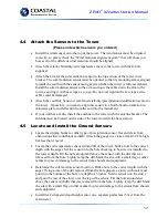
Page 14: ...ox containing the ZENO box radio barometer and to the tower Use the U bolts and the spacers provided to avoid damaging the fiberglass box The NEMA box is mounted on the base of the tower with the bottom of the box at a convenient location above the ground To ground the NEMA box chassis attach the metal clamp to the top of the screw in the tie down stake this is the one that you secured the tower l...

Page 15: ...ination degrees for your geographic location from your magnetic compass measurement You can look this up on the Internet or ask us Each wind sensor has its own marking method to tell you which way to line it up Our most common wind sensors are listed below If you have one different than those shown please contact us for this information NOTE If you have a WEATHERPAK TM it aligns itself automatical...

Page 16: ...ronmental com On the top plate there are letters showing both N North and S South The box on the side should face South The Vane Tail should point North the Cups should point South On the Vane component right in photo above there is a slot at the bottom of the tube that holds the sensor to the cross arm this slot should face South 16 ...

Page 17: ...he antenna bracket The antenna must be located on the side of the tower towards the base station 4 5 Locate and Install the Ground Sensors Locate the tipping bucket or other type of precipitation sensor free and clear from obstructions that could block rainfall Attach the gauge to a stake at least 30 Cm high but less than 1 meter Locate the soil temperature sensor within 20ft of the tower Drill a ...

Page 18: ...there is a possibility of getting moisture inside the box Your station may have been ordered with either MIL SPEC connect connectors or with compression fittings for each cable dorn fittings If you purchased the MIL Spec connectors then simply connect them to the appropriate mating connector on the enclosure If you have dorn fitting then Undo the dorn compression fitting at the base of the NEMA bo...

Page 19: ...ck that all external cables are in good condition and taut If the cables have become slack gather together more cable at the enclosure Check that the cable ties have not become brittle due to UV exposure Replace any brittle ties Apply WD 40 or a similar agent to all hinges and latches on your enclosure Open any NEMA boxes and check the condition of the rubber gasket Change the desiccant before clo...

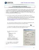
Page 20: ...self however you will need a terminal program to connect You can use HyperTerminal or the UCON software that is shipped with your Weather Station Getting connected To access the ZENO menu structure you need a computer e g a PC or Macintosh with an RS 232 serial port or USB port with adaptor running a communication program such as UCON or the Microsoft Windows Terminal program a cable allowing the ...

Page 21: ... your system It should already be set up with the communication parameters used for your system If not or if you did not receive or have lost your CD you can download the software from http www umonfw com ucon index html and click on the blue uCon link in the upper left corner of the page B Click on the ucon_install exe icon may be in C Documents and Settings User My Documents Downloads and follow...

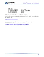
Page 22: ...e appropriate procedure to make the required changes If you have any questions or require additional assistance contact Coastal s Service Department 206 682 6048 x157 support coastalenvironmental com If you wish to make more changes with the weather station software please see the ZENO DATALOGGER manual It is on our website at http www coastalenvironmental com service downloads shtml ...

Page 23: ...Bits per second 9600 if 9600 does not work try another rate Data bits 8 Parity None Stop bits 1 Flow control None Click Apply then OK Your HyperTerminal window should now be connected to the selected com port on your computer The lower left hand side of the window should show Connected with a timer counting up 2 Connect Black Crossover Cable to the maintenance port on the ZENO 3200 Connect the oth...

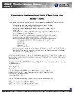
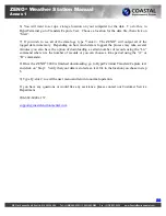
Page 24: ...ending on how much data is logged the process may take several minutes you also have the option of downloading a certain number of records using the Ln command where n is the number of records or you can choose a time period using the A or B commands 8 Once the ZENO 3200 is finished downloading go to HyperTerminal Transfers Capture text and click on Stop Verify that your data is stored as a text f...

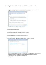
Page 25: ...u to make it your default terminal program click Yes C In the Connection Description window type any name for the connection such as Wthrpk and click OK D In the Connect To window go to Connect using and select Com 3 on your computer Click OK E In the COM X Properties window the select the port settings as follows Bits per second 9600 Data bits 8 Parity None Stop bits 1 Flow control None Click App...

Page 26: ... Interval to 1800 seconds and the Sample Duration to 600 seconds At the start of each sample period the ZENO would process data for 10 minutes then go to low power mode for 20 minutes At the end of the 30 minute sample period the ZENO would log the data and begin a new sample period 7 Once you have made the changes desired you must save them to the EEPROM Type e enter The ZENO should show it is sa...

Page 27: ...he port settings as follows Bits per second 9600 Data bits 8 Parity None Stop bits 1 Flow control None Click Apply then OK Your HyperTerminal window should now be connected to the selected com port on your computer The lower left hand side of the window should show Connected with a timer counting up 2 Use an accurate reference clock set to GMT or local time for comparison 3 Apply power to the ZENO...

Page 28: ...ental com 6 When the date and time have been updated it should be within 2 seconds of the reference clock 7 Type Q enter to exit the User Menu and return to normal operation If you have any questions or need further assistance please contact Coastal Environmental Systems Customer Support department 206 682 6048 x157 support coastalenvironmental com 28 ...

Page 29: ...ly COM 1 Click OK E In the COM X Properties window the select the port settings as follows Bits per second 9600 if this setting does not work try 1200 Data bits 8 Parity None Stop bits 1 Flow control None Click Apply then OK Your HyperTerminal window should now be connected to the selected com port on your computer The lower left hand side of the window should show Connected with a timer counting ...

Page 30: ...ding the Data Records currently stored in Logging Memory To proceed with this change all Log Data Records must first be deleted WARNING All records in data logging memory will be deleted Continue Y N Type Y enter to continue You should see Ready to receive system configuration file Enter Q to abort 7 In HyperTerminal select Transfer then choose Send Text File Locate the Configuration file on your ...

Page 31: ...ng general serial scripts to EEPROM Saving constants to EEPROM 796 out of 2048 bytes used in EEPROM Total EEPROM Writes 22 EEPROM Checksum 203 ZENO PROGRAM MENU S Sensor Menu M Memory Management Menu P Process Menu W Password Menu D Data Output Menu R Reset System T Sensor Timing Loop Menu E Save Parameters To EEPROM O Output Message Timing Menu U User Menu L System Load Menu Q Quit G General Seri...

Page 32: ...omport on your computer usually COM 1 Click OK E In the COM X Properties window the select the port settings as follows Bits per second 9600 if this setting does not work try another rate Data bits 8 Parity None Stop bits 1 Flow control None Click Apply then OK Your HyperTerminal window should now be connected to the selected com port on your computer The lower left hand side of the window should ...

Page 33: ...Choose a location for the Configuration file on your computer select it and click Start Hit any key on your keyboard to continue Your screen should show something similar to the following Zeno 3200 System Setup File Program Version And Date ZENO 3200 using ZENOSOFT V2 02 Sep 10 2002 11 29 41 CS B97B C opyright 1995 2002 Coastal Environmental Systems Seattle WA USA Setup File Date And Time 07 10 09...

Page 34: ... S2 7 PROCESS 1 1 CSS S2 8 PROCESS 1 1 VIS1M S2 1 PROCESS 1 1 VIS_10M S2 2 PROCESS 1 1 VIS_T S2 9 PROCESS 1 2 IPWC P2 1 PROCESS 1 2 15M_PWC P2 1 PROCESS 1 2 1HR_PWC P3 1 PROCESS 1 2 PRECIP P4 1 PROCESS 1 2 CWS P5 1 PROCESS 1 2 CSS P6 1 PROCESS 1 2 VIS_1M P7 1 PROCESS 1 2 VIS_10M P8 1 PROCESS 1 2 VIS_T P9 1 DATA 6 1 0D 0A P1 1 0 0 1 P1 1 P1 1 P1 1 DATA 4 1 P1 1 0 0 1 P1 1 P1 1 P1 1 DATA 3 1 P1 1 0 ...

Page 35: ... Stop Hit any key on your keyboard to continue The screen should show the following SYSTEM LOAD MENU R Receive Configuration From Host Z Zeno Program Menu T Transmit Configuration From Zeno H Help V View Configuration Menus ASCII Precede The R Or T Command With An X For X Modem Transfer e g Enter XR To Receive A Configuration File Via X Modem Type Z enter then Q enter to exit the user menu and ret...

Page 36: ...t using and select TCP IP then enter the Address and the port ID s which are found using the CPRManager Click Apply then OK Your HyperTerminal window should now be connected to the Lantronix device The lower left hand side of the window should show Connected with a timer counting up 2 Connect Test Cable to Com 3 on t he ZENO DB9 connector Connect the other end to a serial Com port on computer 3 Ap...

Page 37: ...ransfer e g Enter XR To Receive A Configuration File Via X Modem xt Starting X Modem File Transfer Hit Control X to halt 8 In HyperTerminal select Transfer then choose Receive File Choose a location for the Configuration file on your computer desk top choose X Modem in the drop down Use receiving protocol menu box and click Receive Hit any key on your keyboard to continue Your screen should show s...

Page 38: ...tal com Precede The R Or T Command With An X For X Modem Transfer e g Enter XR To Receive A Configuration File Via X Modem Type Z enter then Q enter to exit the user menu and return to normal operation If you have any questions or would like any assistance please contact our Customer Service Department 206 682 6048 x157 support coastalenvironmental com 38 ...

Page 39: ...n comport on your computer usually COM 1 Click OK E In the COM X Properties window the select the port settings as follows Bits per second 9600 Data bits 8 Parity None Stop bits 1 Flow control None Click Apply then OK Your HyperTerminal window should now be connected to the selected com port on your computer The lower left hand side of the window should show Connected with a timer counting up 2 Co...

Page 40: ...00 0000 1009 6403 1009 6403 1009 6403 1009 6403 1009 6403 1009 6403 7 Compare the readings from the pressure sensor with the readings from your reference barometer T here should be no m ore than 0 05 m b difference between the ZENO 3200 barometer and the laboratory reference barometer If the ZENO 3200 barometer is determined to be out of tolerance it must be sent to the manufacturer for recalibrat...

Page 41: ...ng and select an open comport on your computer usually COM 1 Click OK E In the COM X Properties window the select the port settings as follows Bits per second 9600 Data bits 8 Parity None Stop bits 1 Flow control None Click Apply then OK Your HyperTerminal window should now be connected to the selected com port on your computer The lower left hand side of the window should show Connected with a ti...

Page 42: ...em 2 2883 Secondary Unit Experiment ID Item 3 1 Data Dump Format Item 4 1 Real Time Output Format Item 5 1 Add Compass To Vane Item 6 6 Compass Offset Item 7 486 Barometer Elevation Item 8 M Bad Sensor Value Replace Item 9 ESC Passthrough Mode Escape Character 9 Type E enter to save the change to the EEPROM You should see something similar to this on your screen Verifying parameters can be stored ...

Page 43: ...e it your default terminal program click Yes C In the Connection Description window type any name for the connection such as Wthrpk and click OK D In the Connect To window go to Connect using and select an open comport on your computer usually COM 1 Click OK E In the COM X Properties window the select the port settings as follows Bits per second 9600 Data bits 8 Parity None Stop bits 1 Flow contro...

Page 44: ...the magnetic deviation for the location of the system installation The magnetic deviation value can be determined from various Internet sites A few can be found at this link on Coastal s website http www coastalenvironmental com magnetic declination shtml 8 Items 5 and 6 of the System Function Menu will need to be changed In the System Function Menu type c5 1 enter Next type c6 xx enter where xx i...

Reviews: