background image

Page  6

Installation and Assembly Guide: 


Norms and Directions 


It is the responsibility of the installation engineer that he has the necessary training and authorisation 
to install the boiler. The size of the boiler should be based on the heating needs of the house rather 
than the size of the fuel container. 

The installation must fulfill the requirements described in the directions of the


Health and Safety at 

Work Act 1974, iincluding the following regulations: The Electricity at work Regs 1989, The Provision 
and Use of Work Equipment Regs 1998, The Personal Protective Equipment Regs 1992, 
The Fire Precautions (Workplace) (Amendments) Regs 1999, The construction Design and 
Management Regs 1994. Current Institute of Electrical Engineers regulations. “The Pressure 
Equipment Directive 97/23/EEC” and UK Building Regulations 2000 (as amended). See in particular 
the following approved documents: 
A: structure 2004 + amendments 
B: fire safety 2000 e amendments 
F: ventilation 2006 edition 
J: combustion appliances and fuel storage systems 2002 edition 
J: Guidance and supplementary information on the UK implementation of European standards for 
chimneys and flues 2002 edition 
L1A; L1B; L2A;L2B: Conservation of fuel and power 2006 edition. 
M: Access to and use of buildings 2004 edition 
P: Electrical Safety – Dwellings – 2006 edition 


If the boiler is used for burning straw, the installation must furthermore fulfill the requirements 
described in the specific directions of The Health and Safety at Work Act 1974


All smoke pipes must have an uphill gradient of minimum 1 %, and all joints must be tight. Never use 
a smaller diameter smoke pipe as the boiler outlet pipe. Always use elbows with a bending and flap as 
bent joints, as they provide the best flue. 

All smoke pipes must be insulated, also when the boiler 

is used with stoker feeding.  


The combustion must not be carried out until the boiler is installed and fully connected. 


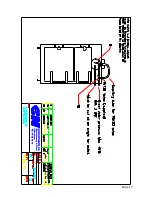
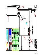
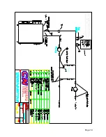
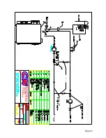
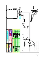
A probe must always be installed on the boiler, and the return pipe (pages 9/11) must always be 
minimum 60° C during operation. See the assembly guide drawing. 


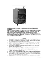
If the right physical conditions are present, the boiler may be installed on a base (approximately 
400 mm high) to make the operation and removal of ashes easier.  


Open or closed system 


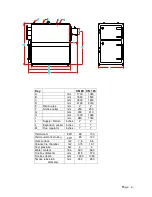
CN boilers type 80 and type 120 are approved for installation as open or closed systems.  


When used as a closed system (with pressure expansion) and open system with a height above 5 
meters, the boiler must be equipped with a cooling spiral and a thermal over temperature valve 
(pages 7 & 8). 


Safety valve requirements in closed systems 


With boilers > 60 kW every boiler must have at least 2 safety valves. The safety valves must be able 
to, in combination at the chosen blow-off pressure, blow off at least 1.5 times the boiler heat yield in 
the form of steam. They must, however, have a minimum internal diameter of 20 mm. 


The inlet and outlet hoses of the safety valves must be of sufficient dimensions for the capacity of the 
safety valves not to be noticeably reduced. The inlet pipe must not contain blocking devices, pumps, 
boiler mountings, restrictions or water sacks.  


All inlet and outlet hoses to and from safety valves must be run through pipes approved for 120 °C 
and minimum 10 bar over pressure. 


Summary of Contents for 120

Page 1: ...Page 1 User Manual for CN Boilers Type 80 120 Machine no Date CN Maskinfabrik A S Skovløkkevej 4 Tiset 6510 Gram Denmark Tel 74 82 19 19 Fax 74 82 19 20 Version April 2005 ...

Page 2: ...nty Claims Page 12 Check List End User Page 13 Check List Supplier Page 14 Check List CN MASKINFABRIK A S Page 15 Warranty Certificate Customer Copy Page16 5 Year Warranty Certificate CN MASKINFABRIK A S Page 17 Principle Diagram Overflow Valve Cooling Spiral Page 18 Principle Diagram Open Expansion with Accumulation Tank Page 19 Principle Diagram Pressure Expansion Without Accumulation Tank Page ...

Page 3: ... surrounded by water The construction and dimensions of the CN boiler thus create an efficient use of the smoke gas before it reaches the smoke outlet The large doors of the CN boiler which open both the fire chamber and the smoke ducts make cleaning the boiler very efficient and easy Optimal environmentally friendly and highly efficient burning of the wood requires correct ratio between the combu...

Page 4: ...480 I mm 980 1180 J Supply Return inches 2 2 L Expansion vessel inches 1 1 M Flue regulator inches 1 1 Yield wood kW 65 100 Yield automatic stoking kW 80 120 Heat surface m2 7 5 9 6 Volume fire chamber m2 0 75 1 07 Test pressure bar 4 4 Water content litre 490 560 Fire box diameter mm 815 970 Fire box depth mm 1450 1450 Smoke tube stub diameter mm 250 250 ...

Page 5: ...illingness and correct attitude to burning wood as it does after all take a bit of work to yield the crops of this environmentally friendly and financially profitable type of heating Safety If any faults or failures are found they must be repaired as soon as possible by a boiler engineer Flue pipes ventilation ducts air holes etc must not be closed off or blocked Flammable liquids or combustible s...

Page 6: ...ave an uphill gradient of minimum 1 and all joints must be tight Never use a smaller diameter smoke pipe as the boiler outlet pipe Always use elbows with a bending and flap as bent joints as they provide the best flue All smoke pipes must be insulated also when the boiler is used with stoker feeding The combustion must not be carried out until the boiler is installed and fully connected A probe mu...

Page 7: ...t the boiler unit must fulfil certain essential safety requirements regarding the safety equipment of the boiler etc The boiler must be fitted with a cooling spiral Expansion vessel The vessel must be installed in accordance with the directions of The Health and Safety at Work Act 1974 The bottom of the expansion vessel should be installed only above pipes radiator of the central heating system an...

Page 8: ...e NTC 2322 2 CN supplied with stoker Overheating thermostat Honeywell type L6188 3 CN supplied with stoker Boiler thermometer 0 120 degrees 4 Installation engineer Pressure gauge manometer 0 3 maximum 5 bar red marks at 2 5 bar 4 Installation engineer Pressure expansion vessel CE labeled minimum 4 of total system water volume see table below 6 Installation engineer Safety valve CE approved 2 pces ...

Page 9: ...ostat BS components type 2322 2 CN supplied with stoker Overheat thermostat Honeywell type L6188 3 CN supplied with stoker Boiler thermometer 0 120 C degrees 4 Installation engineer Pressure gauge manometer 0 3 maximum 5 bar red mark at 2 5 bar 4 Installation engineer Accumulation tank Type approved in acc with Declaration on Installation of Pressurised Equipment 11 Installation engineer Shunt val...

Page 10: ...ed every 24 hours of use If the boiler is switched off for a long period approximately 1 week the boiler and flue pipes should be cleaned thoroughly as the residue combined with damp results in corrosion The pump s must be switched off whilst the system is filled up with water NOTE Do not fill up an overheated boiler with water Installation with pressure expansion water filling until 1 5 2 0 bar I...

Page 11: ...iler thermostat setting range is 55 85 C Water content in 80 120 boiler 490 560 L Boiler classification 3 Set point for boiler thermostat 65 C Warranty Claims CN MASKINFABRIK A S provides a 24 month warranty for the stoker unit following the date of this user manual for the first user The warranty includes materials and manufacturing faults but not wear on parts damages caused by failure to mainta...

Page 12: ...ve received instructions in the maintenance of the boiler Boiler type Serial number Year I hereby declare that I have understood the received material Name ____________________________________ Address ____________________________________ Town and post code ____________________________________ ____________________________________ Signature For End user ...

Page 13: ...eived instructions in the maintenance of the boiler Boiler type Serial number Year I hereby declare that I have understood the received material Name ____________________________________ Address ____________________________________ Town and post code ____________________________________ ____________________________________ Signature Please return to Supplier ...

Page 14: ...rtificate______________ The installation engineer has subjected the boiler unit to a construction test module B1 or installed the boiler unit in accordance with a full quality assurance system module H in accordance with the Pressure Equipment Directive 97 23 EEC _____________________ Boiler type Serial number Year I hereby declare that I have understood the received material Name ________________...

Page 15: ...MASKINFABRIK A S 5 The boiler must a no time have been used for burning grain 6 The boiler must not be exposed to insufficient maintenance incorrect use or overloading 7 CN MASKINFABRIK A S will repair any claims or approve the repair before it is carried out according to the choice of CN The service includes the following Gaskets inspected and checked Doors inspected tightened and adjusted Boiler...

Page 16: ...overloading 7 CN MASKINFABRIK A S will repair any claims or approve the repair before it is carried out according to the choice of CN The service includes the following Gaskets inspected and checked Doors inspected tightened and adjusted Boiler cleaned and inspected Installation inspected Smoke pipe inspected and checked Any fire resistant materials inspected and checked Cleaning tools inspected a...

Page 17: ...Page 17 ...

Page 18: ...Page 18 MASKINFABRIK A S Skovløkkevej 4 Tiset 6510 Gram Tlf 74 82 19 19 MASKINFABRIK A S Skovløkkevej 4 Tiset 6510 Gram Tlf 74 82 19 19 Check valve Draining ...

Page 19: ...SKINFABRIK A S Skovløkkevej 4 Tiset 6510 Gram Tlf 74 82 19 19 This drawing is a principle diagram Hence CN Maskinfabrik A S cannot be made responsible for faults errors or losses based on this diagram Check valve ...

Page 20: ...SKINFABRIK A S Skovløkkevej 4 Tiset 6510 Gram Tlf 74 82 19 19 This drawing is a principle diagram Hence CN Maskinfabrik A S cannot be made responsible for faults errors or losses based on this diagram Check valve ...

Page 21: ...SKINFABRIK A S Skovløkkevej 4 Tiset 6510 Gram Tlf 74 82 19 19 This drawing is a principle diagram Hence CN Maskinfabrik A S cannot be made responsible for faults errors or losses based on this diagram Check valve ...

Reviews: