background image

3

2D. Electrical 

Refer to the 

IMPORTANT SAFETY INSTRUCTIONS

 at the beginning of this manual for important wiring information.

2D-1. Main Power

•  Connect the UV-C Pro so that it operates simultaneously with the pool pump. 

•  An electrical junction box and wires are provided on the left wall of the enclosure for a 1/2” conduit connection. 

•  Remove the protective plug and install electrical fittings as required to meet local codes. 

•  Run service wires to the box and connect to provided wiring. 

2D-2. Bonding Lug

Connect a solid copper conductor to the bonding lug on the left side of the UV-C Pro to an appropriate earth contact. 

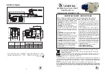
(Figure 1)

Figure 2: Remote Contact Locations

2D-3. System Control

•  Remote start contacts have been provided for remote ON-OFF operation of the UV-C Pro.  

•  These should be wired to an external device that closes when the pool pump is ON and opens when it is OFF. 

•  Failure to use the remote start contacts may result in damage to the unit not covered under warranty.

2E. Plumbing

The UV-C Pro can easily be added into the pool’s plumbing loop.  All the components are contained inside the enclosure 

so only the water inlet and outlet need to be installed into the pool’s return line.

IMPORTANT! Plumbing inlet and outlet layout may vary from UV-C PRO-500D model shown in Figure 1. Always plumb 

flow according to the marking on the unit.

2E-1. Plumbing the UV-C Pro

•  Install in the main return line of the pool immediately after the filter and preferably before the heater.

•  Install cleaners such as chlorinators after the UV-C Pro. 

•  The outlet of the UV-C Pro must be at least 10 feet from the first return of the pool.

•  Use the fittings provided in the parts kit to connect the UV-C Pro inlet and outlet to the plumbing.

Connection Points for


Remote Start Contacts

2. INSTALLATION

Summary of Contents for DEL AOP PRO 200

Page 1: ...4 2813 01 Rev A CMPCOMMERCIAL COM DEL UV C PRO 200 350 500 INSTALLATION INSTRUCTIONS PRODUCT MANUAL...

Page 2: ...ssible to anyone in the pool Never attempt any servicing while unit is wet For your safety do not store or use gasoline chemicals or other flammable liquids or vapors near this or any other appliance...

Page 3: ...on 4 3C System Shut Down 6 3D Water Chemistry 6 4 Maintenance Service 4A System Electromechanical Overview 7 4B UV Reactor Service and Maintenance 7 4C PLC Memory Battery Backup Replacement 10 4D Wint...

Page 4: ...esults UV C is compatible with all traditional sanitizers These systems are cost effective to operate and maintain UV C Pro is NSF certified for supplemental disinfection of pools and spas UV C PRO 20...

Page 5: ...a protected from rain and direct sunlight Locate the unit out of reach of sprinklers or drainage spouts Allow sufficient access for maintenance 2 ft clearance above and 1 ft around the unit and all pl...

Page 6: ...to an external device that closes when the pool pump is ON and opens when it is OFF Failure to use the remote start contacts may result in damage to the unit not covered under warranty 2E Plumbing The...

Page 7: ...screen includes status indicators and text to communicate real time system conditions as well as access to historical data The five function buttons allow user navigation of the menus and user input T...

Page 8: ...lert reminders More than 10 remaining no banner message 10 remaining SERVICE SOON banner message 5 remaining SERVICE REQUIRED banner message 0 remaining SERVICE PAST DUE alert banner message with yell...

Page 9: ...Followed for servicing or storage 1 Shut off water flow to the unit and or close isolation valves if available 2 Shut off power at the breaker 3 Open enclosure door to access internal components NOTE...

Page 10: ...p is difficult to remove use a slight twisting motion or remove the lamp retainer AVOID TOUCHING THE UV LAMP GLASS WITH YOUR BARE HANDS Oils on your hands can cause hot spots on the UV lamp and shorte...

Page 11: ...8 4 MAINTENANCE SERVICE Inlet Flange Outlet Flange Flow Switch Location not shown Ballast UV Reactor Figure 3 UV C Pro Electro Mechanical Overview...

Page 12: ...emoval Figure 5 UV Quartz Tube lnstallation NOTE DAMAGES CAUSED BY BROKEN QUARTZ TUBES ARE NOT COVERED UNDER THE LIMITED WARRANTY UV Lamp Quartz Tube Lamp Retainer Sealing O ring Lamp Retainer Screws...

Page 13: ...tom of the quartz tube 3 Connect the UV lamp connector to the connector on the ballast ENVIRONMENTAL NOTICE Hg Lamp CONTAINS MERCURY Manage in accordance with disposal laws See www lamprecycle org Fig...

Page 14: ...box b Check for loose connections or wiring breaks in the main power wiring leading to the UV C Pro c Check internal circuit breaker Symptom SYSTEM WAITING ON REMOTE START CONTACTS message 1 Remote s...

Page 15: ...u call 1 800 733 9060 or visit www cmpcommercial com 5D Standard Replacement Parts List DESCRIPTION PART NUMBER REPLACEMENT INTERVAL PLC MEMORY BACKUP BATTERY included with PLC option only 5 1402 Annu...

Page 16: ...Pro Pressure Drop Characterization NOTE Tested on simulated recirculation system using a variable speed pump No back pressure added Actual results will vary depending on pump and plumbing variables AP...

Page 17: ...utlet unions or flanges b Flow the cleaning solution from bottom to top 2 When cleaning is complete drain the UV C Pro completely from the inlet union or flange and run the pool system immediately for...

Page 18: ...Below Keep for Your Records Installer _______________________________________________________________ System Purchased From ______________________________________________ Installation Date __________...

Page 19: ...16 NOTES...

Page 20: ...CMP LLC 36 HERRING ROAD NEWNAN GA 30265 WWW CMPCOMMERCIAL COM 1021ab...

Reviews: