


MAN. 161 rev. 5 Use and maintenance manual Sup15
16ª
page of
77
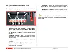
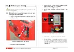
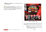
- Start button
1
(Picture 9): pushing this button (green) the ther-
mic (or electrical) motor starts.
- Emergency stop switch
2
(Picture 9) it blocks the machine un-
feeding the control circuits; the machine has a mechanical block-
ing device, therefore, to reset its operability, it is necessary to un-
block the switch turning it clockwise. This switch has the priority
on any other control; it is only allowed to manually descend on the
ground.
- platform control station - consent led light
3
(Picture 9):
green light: the green light on indicates the consent to the use of
the station controls;
- "load sensing" led light
4
(Picture 9): red light : the light on in-
dicates that the platform is locked because is overloaded (>200
Kg):
OPTIONAL
;
-”Dead man” switch – levelling operation consent
5
(Picture 9): for the levelling operation it is necessary to push
this button together with the lever
6
(Picture 9);
- Joystick lever for jib lifting control /basket levelling
6
(Picture 9): it carries out the aforementioned operations; pushed
together with the “dead man” switch
5
(Picture 9) it carries out the
levelling;
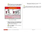
Perform the basket levelling operation only when the MEWP
aerial part is in the transport configuration.
It is strictly forbidden to carry out the basket levelling opera-
tion when the machine is open.
- Joystick lever for turret rotation control
7
(Picture 9)
- Joystick lever for extension control
8
(Picture 9)
- Arm lifting control lever
9
(Picture 9)
- Joystick lever for pantograph lifting control
10
(Picture 9)
- stabilization control station - led light
11
(Picture 9): green
light: the green light on, indicates that the stabilization is ok;
-220V socket
12
(Picture 9) (For England: 110 V)
Overload signal spy light could be supplied/mounted
as an
OPTIONAL.
Summary of Contents for SUP15
Page 8: ...MAN 161 rev 5 Use and maintenance manual Sup15 8ª page of 77 Picture 4 stabilization area mm ...
Page 70: ...MAN 161 rev 5 Use and maintenance manual Sup15 70ª page of 77 10 10 Notes ...
Page 72: ...MAN 161 rev 5 Use and maintenance manual Sup15 72ª page of 77 ...
Page 73: ...MAN 161 rev 5 Use and maintenance manual Sup15 73ª page of 77 ...
Page 74: ...MAN 161 rev 5 Use and maintenance manual Sup15 74ª page of 77 ...
Page 75: ...MAN 161 rev 5 Use and maintenance manual Sup15 75ª page of 77 ...
Page 76: ...MAN 161 rev 5 Use and maintenance manual Sup15 76ª page of 77 ...


