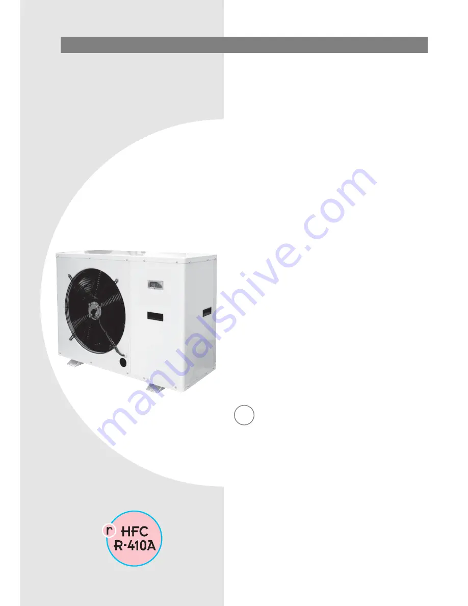
INSTALLATION - OPERATING - SERVICE MANUAL
Reverse-cycle air/water heat pumps withdomestic hot water production, axial-flowfans and water pump assembly.
GB
AWR MTDAWR MTD/B0011÷0061
Page 1: ...INSTALLATION OPERATING SERVICE MANUAL Reverse cycle air water heat pumps with domestic hot water production axial flow fans and water pump assembly GB AWR MTD AWR MTD B 0011 0061...
Page 2: ...he product 4 Description of standard unit 5 Dimensioned drawings 6 Installation 6 Water connections 7 Water circuit data 9 Operating diagrams 12 Electrical connections 14 Mains power supply connection...
Page 3: ...ol devices without authori sation and instructions from the manufacturer Do not pull detach or twist the electrical cables coming from the unit even when disconnected from the mains electricity supply...
Page 4: ...nual is an integral part of the unit and should therefore be read and kept carefully The packaging should not be removed until the unit is located in the installation site Do not dispose of packaging...
Page 5: ...ssem bly complete with electric heaters AWR MTD B Reverse cycle air water heat pump with domestic hot water production Built in water pump assem bly without electric heaters The S at the end indicates...
Page 6: ...dling the unit check the capacity of the lift equip ment used respecting the instructions on the packaging To move the unit horizontally make appropriate use of a lift truck or similar bearing in mind...
Page 7: ...expansion vessel Failure to install the flow switches will mean the heat exchangers are not protected in the event of no flow of liq uid Climaveneta cannot be held liable for any damage to the unit an...
Page 8: ...be fitted with low loss headers The manufacturer is not liable for obstruction breakage or noise resulting from the failure to install filters or vibration dampers Particular types of water used for...
Page 9: ...8 Fouling factors m2 C W f1 Evaporator fk1 fx1 FILLING THE SYSTEM Before starting to fill place the unit mains switch QF1 in the OFF position Before filling check that the system drain valve is closed...
Page 10: ...the system or source subtract the pressure drop of the heat exchangers see the graph Heat exchanger pressure drop system 2 4 6 8 10 10 20 30 40 50 60 70 80 90 100 110 120 130 140 Hp kPa Q m3 h B A A...
Page 11: ...c valve 6 Pump SXM 32 50 7 Plate heat exchanger WP 24 40 8 1 1 4 GAS attachment for optional electric heater 9 Automatic vent valve 3 4 GAS 10 Expansion vessel 18 litres 11 Flexible polyurethane insul...
Page 12: ...anaging a special 3 way valve connected to a hot water storage cylinder 1 Heat pump AWR MTD 2 Non return valve 3 Control valve with dial 4 Shut off valve 5 Expansion vessel if necessary 6 Air separato...
Page 13: ...pecial 3 way valve connected to a hot water storage cylinder 1 Heat pump AWR MTD 2 Non return valve 3 Control valve with dial 4 Shut off valve 5 Expansion vessel if necessary 6 Air separator 7 DHW sto...
Page 14: ...act opening of at least 3mm with ade quate switching and residual current protection capacity based on the electrical data table shown below must be installed as near as possible to the appliance An e...
Page 15: ...n the inspection panel Check that all the covers removed to make the electrical connections have been replaced before powering up the unit Place the main switch QF1 outside the unit in the ON position...
Page 16: ...ermal overload switch QF1 Unit thermal overload switch QF2 3 Auxiliary heating element thermal overload switch MTD version only QS1 Door lock disconnect switch KA2 KA3 KA4 A1 Radio interference suppre...
Page 17: ...the 12VDC red terminal on the keypad To avoid interference due to magnetic fields the use of shielded cable is recommended The cable should not be more than 100 m long CONNECTING A FLOW SWITCH F3 If...
Page 18: ...PE N 1 2 3 U N 4 5 6 7 8 9 10 11 12 13 14 15 16 17 18 19 20 21 22 2324 SA1 SA2 F3 BT4 A4 to GndSignal 12Vdc RD1 GN1 KM4 YV2 N L 230 VAC 1A max Blue Black Brown Y G PE TERMINAL BLOCK AWR 0025 0041 MTD...
Page 19: ...se FU3 Auxiliary circuit protection fuse FU4 230 24 12 VAC transformer protection fuse FU5 Board power supply protection fuse GN1 Green compressor ON light KA2 Hot water storage heater relay KA3 High...
Page 20: ...switch F4 Water differential pressure switch FU1 System water pump protection fuse FU2 Fan protection fuse FU3 Heater protection fuse FU4 230 24 12 VAC transformer protection fuse FU5 Board power supp...
Page 21: ...er protection fuse FU4 230 24 12 VAC transformer protection fuse FU5 Auxiliary circuit protection fuse GN1 Green compressor ON light KA2 Hot water storage heater relay KA3 High pressure switch relay K...
Page 22: ...F4 Water differential pressure switch FU1 System water pump protection fuse FU2 Fan protection fuse FU3 Heater protection fuse FU4 230 24 12 VAC transformer protection fuse FU5 Auxiliary circuit prot...
Page 23: ...sformer protection fuse FU5 Auxiliary circuit protection fuse GN1 Green compressor ON light KA1 Phase sequence control relay KA2 Hot water storage heater relay KA3 High pressure switch relay KA4 R3 en...
Page 24: ...re switch FU1 System water pump protection fuse FU2 Fan protection fuse FU3 Heater protection fuse FU4 230 24 12 VAC transformer protection fuse FU5 Auxiliary circuit protection fuse GN1 Green compres...
Page 25: ...eat exchanger outlet temperature sensor is less than 4 C The frost prevention temperature set point can be modified by an authorised service centre only and only after verifying that the water circuit...
Page 26: ...if activated by parameter Changeover from domestic hot water production to heating system hot water production if the DHW storage temperature sensor BT4 has reached the DHW set point AS01 3 way valve...
Page 27: ...AT PUMP HEATERS AWR MTD MODELS ONLY The AWR MTD unit is fitted with electric heaters with the following power ratings The heaters can be activated as a replacement or additional source of heat as desc...
Page 28: ...Anti Legionella cycle duration for Thursday AS35 2 Anti Legionella cycle start hours for Thursday AS36 0 Anti Legionella cycle start minutes for Thursday ANTI LEGIONELLA FUNCTION The Anti Legionella...
Page 29: ...ture Graph with factory settings Outside air temperature Ds06 Ds02 10 C Ds06 5 C 28 C 33 C Water temperature set point Ds02 15 C Ds04 5 C Parameter Value Unit of measure Description ds00 1 Enable syst...
Page 30: ...6 tE17 6 min 00 tE18 0 hours 7 tE45 6 min 00 tE46 0 tE73 tE74 Operating mode ON Standby ON tE19 0 ON tE47 0 tE75 TIME BAND 2 Cool set point tE20 12 tE48 12 tE76 Heat set point tE21 33 tE49 33 tE77 DH...
Page 31: ...87 2 49 2 82 3 15 Useful pressure head 1 kPa 60 88 75 53 75 53 54 40 Cooling capacity 3 kW 6 5 8 4 11 8 14 11 9 14 5 16 9 18 7 Power input 3 kW 1 9 2 7 3 3 4 1 3 1 4 2 4 7 5 5 E E R 3 42 3 11 3 58 3...
Page 32: ...ax 3 8 C Water circuit pressure min max 1 3 bar Maximum glycol percentage 40 OPERATING LIMITS Heating 15 30 40 50 55 5 7 45 Outlet water temperature C Outside air temperature C Cooling 10 12 0 7 18 35...
Page 33: ...the remote keypad A4 see wiring diagram shows OFF if featured Close the door of the electrical panel Move the main unit switch QS1 to the ON position Move the switch QF1 outside the unit to ON The me...
Page 34: ...ack to previous level See section on Changing new settings operating mode Set Confirm Confirms value exit and save Main display Main Display Menu save new settings new settings See Main Display sectio...
Page 35: ...MODE LEDS Compressor 1st auxiliary heating element stage activation 2nd auxiliary heating element stage activation Fan System pump Domestic hot water function activation External auxiliary heating ele...
Page 36: ...ck for managing time bands to control specific events Follow the procedure shown below to set the hours minutes and date To enter menu CL press the set button Once having entered this menu HOUr will b...
Page 37: ...37 GB 01 2009 AWR MTD AWR MTD B press the set button To exit the clock setting menu press the esc button until returning to the main display...
Page 38: ...cool Use the up and down buttons to select the desired operating mode SELECTING THE OPERATING MODE There are three different modes Standby mode StbY in standby the compressor and pump are off but all...
Page 39: ...ing the SP directory To enter the SP directory press the set button SETTING THE SET POINTS As an example the Set Point in COOL mode will be changed from 12 0 degrees centigrade to 12 5 degrees centigr...
Page 40: ...The instrument will display the current set point in this case 12 0 degrees centigrade To increase or decrease the value use the up and down buttons For example to change the set point to 12 5 degrees...
Page 41: ...ogue inputs config ured as digital inputs the value will be 0 input inactive for digital inputs this corresponds to the input being open for analogue inputs configured as digital inputs it corresponds...
Page 42: ...hen enter the password installer or manufacturer press set and exit Access the parameters to display or change the values Press the up and down buttons to select the Par submenu Press the set button t...
Page 43: ...bels using the up and down buttons until reaching label Hr DISPLAYING AND RESETTING COMPRESSOR PUMP HOURS Press the set button to display the first label in this case the operating hours for compresso...
Page 44: ...hing MANUAL RESET To reset the alarm manually press the UP and DOWN but tons at the same time UP DOWN NOTE resetting an alarm that is still active saves the event in the alarm log MUTING AND MANUALLY...
Page 45: ...case the first alarm is Er01 Scroll any other active alarms using the UP and DOWN buttons NOTE the menu is not cyclical For example if alarms Er01 Er02 and Er03 are active the display will be Er01 Er0...
Page 46: ...ll to the directory FnC Press the set button to access the Functions menu The first label displayed is dEF Use the UP and DOWN buttons to select directory EUr Press the set button for 3 seconds The di...
Page 47: ...0 PL22 Forced capacity control tE PAR tE tE00 AL92 Time bands AL ALarm AL00 AL82 Alarms Note when setting the parameters the COMPRESSOR and HEATER LEDs will flash alternating with the DEFROST LED FAUL...
Page 48: ...atic reset Check electrical connections Replace component Values display indication Er60 Faulty BT1 water return sensor automatic reset Check electrical connections Replace component SHUTTING DOWN FOR...
Page 49: ...R410A refrigerant must only be charged in the liq uid state Operating conditions other than rated conditions may produce considerably different values Tightness testing or identification of leaks mus...
Page 50: ...mponent Check Check Check Protection devices trip and shut down the com pressor Excessive discharge pressure Low suction pressure Low voltage Electrical connections not sufficiently tight Operation ou...
Page 51: ...ater inlet temperature Thermostatic expansion valve faulty or excessively open Check High discharge pressure greater than 23 bars High outside water temperature High utility water inlet temperature In...
Page 52: ...la Mauldre 78680 Ep ne France T l 33 0 1 30 95 19 19 Fax 33 0 1 30 95 18 18 info climaveneta fr www climaveneta fr Climaveneta Deutschland Rhenus Platz 2 59439 Holzwickede Germany Tel 49 2301 91222 0...