ClimateMaster Trilogy VE 0930 Installation, Operation & Maintenance Instructions Manual Download Page 1

97B0119N01

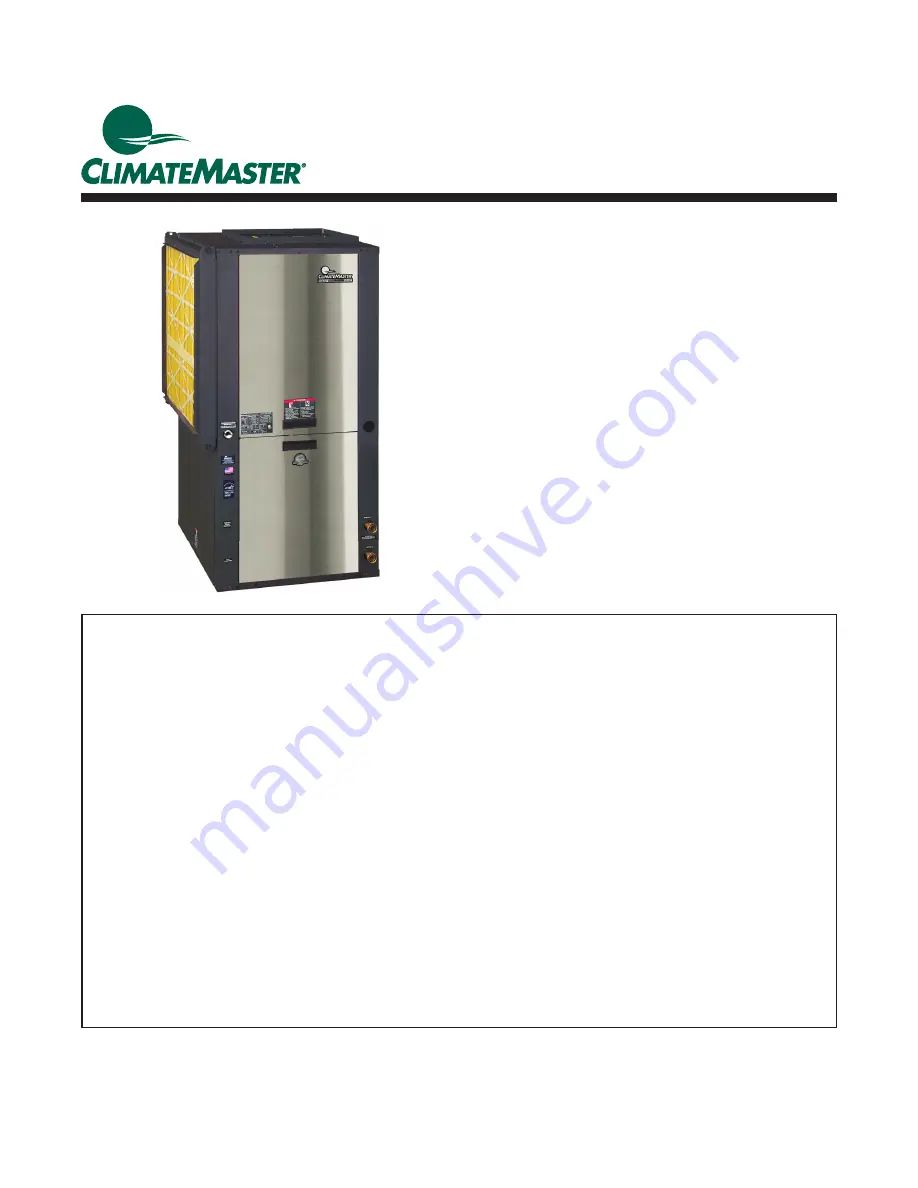
Residential Horizontal, Vertical & Downfl ow

Packaged Geothermal Heat Pumps 

Installation, Operation &

Maintenance Instructions

Created: 4 October, 2019

Trilogy

® 

Variable

(VE) Series IOM

Table of Contents

Model Nomenclature  

3

General Information  

4

Vertical Installation  

5-6

Horizontal Installation  

7-10

Condensate and Water Connection  

11

vFlow

 Heat Pump Applications Overview  

12

Closed Loop Heat Pump Applications 

with Internal Flow Controller  

13-14

Flushing the Earth Loop  

15-17

Multiple Unit Piping and Flushing  

18-20

Ground Loop Heat Pump Applications  

21-22

Electrical - Line Voltage  

23

Electrical - Low Voltage Wiring  

24

Electrical - Thermostat Wiring  

25

EXM Wiring Diagram  

26-27

ECM Blower Control  

28

ECM Blower Performance Data  

29

System Confi guration  

30-34

Unit Commissioning and Operating Conditions  

35

Unit Start-Up and Operating Conditions  

36

Unit Start-Up Procedure  

37

Unit Operating Conditions  

38-39

Performance Data - 0930 - Heating  

40-41

Performance Data - 0930 - Cooling  

42-43

Performance Data - 1860 - Heating  

44-45

Performance Data - 1860 - Cooling  

46-47 

Performance Tables Legend 

48

Preventive Maintenance  

49

Troubleshooting  

50-59

Refrigeration Troubleshooting Form - Heating  

60-61

Refrigeration Troubleshooting Form - Cooling  

62-63

Warranty  

64

Revision History  

68

Summary of Contents for Trilogy VE 0930

Page 1: ...op Heat Pump Applications 21 22 Electrical Line Voltage 23 Electrical Low Voltage Wiring 24 Electrical Thermostat Wiring 25 EXM Wiring Diagram 26 27 ECM Blower Control 28 ECM Blower Performance Data 2...

Page 2: ...This page was intentionally left blank...

Page 3: ...f the equipment DANGER Indicates an immediate hazardous situation which if not avoided will result in death or serious injury DANGER labels on unit access panels must be observed WARNING Indicates a p...

Page 4: ...shipped 2 Keep the cabinet covered with the original packaging until installation is complete and all plastering painting etc is finished 3 Verify refrigerant tubing is free of kinks or dents and that...

Page 5: ...tical Unit Location Packaged units are not designed for outdoor installation Locate the unit in an INDOOR area that allows enough space for service personnel to perform typical maintenance or repairs...

Page 6: ...to all removable panels is not required installer should take care to comply with all building codes and allow adequate clearance for future field service 2 Front Side access is preferred for improve...

Page 7: ...ommodate the service technician during the removal or replacement of the compressor and the removal or installation of the unit itself 2 Provide access to hanger brackets water valves and fittings Pro...

Page 8: ...onal 2 service access Air Coil Front Front Front Front CAP CAP Notes 1 While clear access to all removable panels is not required installer should take care to comply with all building codes and allow...

Page 9: ...ariable Speed Pump Insulated supply duct with at least one 90 deg elbow to reduce air noise Water Out Water In by others Unit Power Disconnect by others Power Wiring Supply Air 3 8 10mm threaded rods...

Page 10: ...move the screws as shown in Figure 7 to free top panel and discharge panel 2 Lift out the access panel and set aside Lift and rotate the discharge panel to the other position as shown being careful wi...

Page 11: ...THE CONDENSATE FLOW Gasket Swivel Nut Stainless steel snap ring Brass Adaptor Hand Tighten Only Do Not Overtighten Figure 10 Water Connections 2 1 5 1 5 1 8 Per Foot Water Connections Residential Dis...

Page 12: ...low control The factory installed high efficiency variable speed pump uses 60 80 less wattage than a traditional fixed speed pump vFlow technology improves performance of the unit by reducing the amou...

Page 13: ...flush the unit The variable speed pump is controlled by the EXM board based on the difference between the entering and leaving water temperature T For operation outside of the normal entering water te...

Page 14: ...Hz HFC 410A C reate d 4 O ctober 2019 Closed Loop Heat Pump Applications with Internal Flow Controller Figure 13a High Head Variable Pump with Check Valve 0 5 10 15 20 25 30 35 40 45 0 5 10 15 20 25 H...

Page 15: ...debris that might clog damage the heat exchanger or pump is removed See Table 1 for flow rate required to attain 2fps 0 6 m s The steps below must be followed for proper flushing Units with internal...

Page 16: ...to help purge air pockets from the piping system Notice the drop in fluid level in the flush cart tank If all air is purged from the system the level will drop only 3 8 in a 10 25 4 cm diameter PVC fl...

Page 17: ...ctuate with the seasons and pressures will be higher in the winter months than during the cooling season This fluctuation is normal and should be considered when charging the system initially Unhook t...

Page 18: ...shing mode We know from Table 2 that the Cv for the flushing valve in a VE0930 is 10 3 in the flushing mode 90 flow Therefore P GPM Cv 2 16 10 3 2 2 4 psi per valve there are two flushing valves So lo...

Page 19: ...tion can generally be employed for systems to 12 tons depending on loop design However it is important perform appropriate calculations to confirm that the variable speed pump can provide adequate flo...

Page 20: ...on Flushing Ports Water Out Water In Heat Pump B Water Out Water In Heat Pump A To Ground Loop Water Out Water In Heat Pump C Ground Loop Shut Off Valve Indoor Loop Shut Off Valve Flush Valve Size for...

Page 21: ...n 1 Flush loop until all air has been purged from system and pressurize to check for leaks before adding any antifreeze 2 Run discharge line to a drain and hook up antifreeze drum to suction side of p...

Page 22: ...the loop and flush until fluid is homogenous and mixed It is recommended to run the unit in the heating and cooling mode for 15 20 minutes each to temper the fluid temperature and prepare it for pres...

Page 23: ...wiring Unit terminals are not designed to accept other types of conductors Unit Power Supply see electrical tables 7a 7b for minimum circuit amps and maximum breaker size VE Model Rated Voltage Compre...

Page 24: ...elay Connections K7 Relay Acc2 Relay Acc1 Relay Test Button To Speed Up Time Delays S 1 Dipswitches Fault and Status LEDs Figure 20 Trilogy Low Voltage Field Wiring Table 8 Accessory Relay Configurati...

Page 25: ...l cavity Position the thermostat back plate against the wall so that it appears level and so the thermostat wires protrude through the middle of the back plate Mark the position of the back plate moun...

Page 26: ...VE Series IOM 60Hz HFC 410A C reate d 4 O ctober 2019 EXM Wiring Diagram 96B0005N70 Part 1 of 2 This diagram includes typical wiring details but is not applicable to all units For specific unit wirin...

Page 27: ...27 climatemaster com Trilogy Variable VE Series IOM 60Hz HFC 410A Created 4 October 2 0 1 9 EXM Wiring Diagram 96B0005N70 Part 2 of 2...

Page 28: ...determined by the unit model capacities selected for Minimum Heating Capacity Maximum Heating Capacity Minimum Cooling Capacity and Maximum Cooling Capacity The available airflow settings are Minimum...

Page 29: ...525 525 525 15 000 650 650 650 18 000 750 750 750 21 000 850 850 850 24 000 975 975 975 27 000 1075 1075 1075 30 000 1125 1125 1125 1860 0 45 at 2250 0 75 at 2000 1 Default 18 000 600 525 600 700 150...

Page 30: ...various devices such as a furnace or air conditioner that are being connected An access code is required to enter the Installation Settings menu from the iGate Connect thermostat The access code is 47...

Page 31: ...e heating Valid range 0 0 F to 5 0 F Default is 1 0 F Anticipator Configures the sensitivity of the thermostat to the space temperature A lower setting will cause the unit to respond more rapidly to c...

Page 32: ...ge Pressure displays the refrigerant discharge pressure Discharge Saturation displays the saturation temperature of the refrigerant discharge pressure Discharge Temp displays the temperature of the co...

Page 33: ...is sensor number 1 It will not display a name until a name has been entered Name Establishes a name for sensor 1 Type Configures the type of sensor The sensor may be a dry contact or a temperature se...

Page 34: ...ftware includes three pages of configura tion data for your Trilogy and the following are values that can be configured on these pages 1 Equipment a Unit family blower type loop config b Loop delta T...

Page 35: ...rating conditions Minimum maximum limits are start up conditions to bring the building space up to occupancy temperatures Units are not designed to operate under these conditions on a regular basis Co...

Page 36: ...Check and adjust water pH if necessary to maintain a level between 6 and 8 5 Proper pH promotes system longevity see Table 5 System flushing Verify that all air is purged from the system Air in the sy...

Page 37: ...thin a few minutes after the unit has begun to operate c Check the elevation and cleanliness of the condensate lines Dripping may be a sign of a blocked line Check that the condensate trap is filled t...

Page 38: ...4 0 5 0 17 23 10 139 144 343 363 8 12 11 16 5 5 6 5 17 23 110 20 135 140 476 496 8 12 13 18 2 7 3 7 17 23 15 136 141 454 474 8 12 12 17 4 3 5 3 17 23 10 137 142 432 452 8 12 12 17 5 9 6 9 17 23 0930...

Page 39: ...4 13 4 17 23 10 123 133 342 362 8 12 9 14 12 2 13 2 17 23 110 20 112 122 477 497 8 12 12 17 13 6 14 6 17 23 15 115 125 454 474 8 12 12 17 13 4 14 4 17 23 10 117 127 432 452 8 12 11 16 13 1 14 1 17 23...

Page 40: ...43 0 52 0 75 1 04 1 38 7 5 10 2 15 4 20 5 25 3 6 1 6 7 7 0 6 8 6 4 7 500 9 3 12 0 18 0 24 0 30 0 0 38 0 46 0 69 1 00 1 36 8 0 10 4 15 6 20 6 25 4 7 1 7 7 7 6 7 0 6 5 80 13 300 9 0 12 0 18 0 24 0 30 0...

Page 41: ...63 0 63 0 63 0 63 0 63 0 2 1 2 8 4 3 5 7 7 1 1 6 3 2 5 1 25 33 48 62 74 63 0 63 0 63 0 63 0 63 0 2 1 2 9 4 4 5 8 7 2 1 8 3 4 5 3 25 32 46 60 72 63 0 63 0 63 0 63 0 63 0 2 3 3 0 4 5 5 9 7 2 1 8 3 4 5...

Page 42: ...0 24 0 30 0 6 8 9 1 13 6 18 0 21 9 0 76 0 75 0 76 0 75 0 73 0 28 0 35 0 54 0 84 1 27 10 0 13 2 19 8 26 9 34 3 10 500 10 1 12 0 18 0 24 0 30 0 9 1 11 0 15 5 19 1 24 0 0 90 0 92 0 86 0 79 0 80 0 25 0 2...

Page 43: ...0 1 1 1 4 2 1 2 9 3 7 1 2 19 6 20 9 20 2 17 8 15 4 30 38 56 76 93 100 0 100 0 100 0 100 0 100 0 1 1 1 4 2 1 2 9 3 7 1 2 20 5 22 9 21 0 17 6 15 1 28 35 53 72 90 100 0 100 0 100 0 100 0 100 0 1 0 1 4 2...

Page 44: ...35 3 29 15 8 20 5 30 6 40 0 48 8 6 5 6 9 6 7 6 0 5 3 7 500 19 2 24 0 36 0 48 0 60 0 0 75 0 91 1 49 2 30 3 40 16 7 20 9 30 9 40 1 48 4 7 5 7 7 7 1 6 1 5 2 80 13 300 18 8 24 0 36 0 48 0 60 0 0 99 1 16 1...

Page 45: ...3 0 63 0 63 0 63 0 63 0 4 1 5 6 8 4 11 1 13 7 2 7 5 9 10 3 20 25 38 51 64 63 0 63 0 63 0 63 0 63 0 4 5 5 9 8 7 11 4 13 9 3 0 6 4 10 8 20 24 37 50 63 63 0 63 0 63 0 63 0 63 0 4 8 6 0 8 8 11 5 13 8 3 1...

Page 46: ...18 0 24 0 36 0 48 0 60 0 12 8 17 3 26 0 34 3 41 9 0 71 0 72 0 72 0 71 0 70 0 55 0 72 1 18 1 89 2 93 19 9 26 5 40 0 54 4 70 0 10 500 19 3 24 0 36 0 48 0 60 0 15 6 18 9 29 0 39 2 46 1 0 81 0 79 0 81 0...

Page 47: ...5 15 5 12 8 23 31 47 66 87 100 0 100 0 100 0 100 0 100 0 2 1 2 8 4 3 5 9 7 6 1 9 20 7 24 5 19 0 14 1 11 8 22 29 45 63 85 100 0 100 0 100 0 100 0 100 0 2 1 2 7 4 2 6 0 7 7 2 0 23 0 24 4 21 9 18 2 15 2...

Page 48: ...eat of rejection Mbtuh DT temperature difference HZ compressor hertz HE total heat of extraction Mbtuh WPD Water coil pressure drop ft hd EER Energy Efficiency Ratio BTU output Watt input COP Coeffici...

Page 49: ...w once per month using a high pressure wash similar to those found at self serve car washes Condensate Drain In areas where airborne bacteria may produce a slimy substance in the drain pan it may be n...

Page 50: ...92 21 69 8 11 94 91 195 8 0 89 22 71 6 11 42 92 197 6 0 86 23 73 4 10 92 93 199 4 0 84 24 75 2 10 45 94 201 2 0 81 25 77 0 10 00 95 203 0 0 79 26 78 8 9 57 96 204 8 0 76 27 80 6 9 16 97 206 6 0 74 28...

Page 51: ...hmmeter WHITE RED GREEN RED YELLOW VIOLET and BLUE VIOLET should each read between 36 and 44 ohms HT Improperly functioning EEV1 Check output signal from EXM CL Improperly functioning EEV2 Check coil...

Page 52: ...rize loop ALL Air pocket Flush and repressurize loop ALL System setup for single and not parallel pumping Change unit loop pump configuration ALL Pump Failure Check pump ALL Bad Flow Sensor Check flow...

Page 53: ...ze ALL Incorrect motor size Check motor size 21 High Blower Static ALL Plugged air filter Clean or replace air filter ALL Bad duct work Correct duct work 22 Grundfos Flow Sensor ALL Bad tranducer If s...

Page 54: ...ce curve per calculator ALL Bad wiring harness Check wiring harness ALL Bad EXM If harness and sensor are fine board is bad replace EXM 42 Air Coil Liquid temp Sensor ALL Bad thermistor Check temp vs...

Page 55: ...emp out of range Bring air temp within design parameters ALL Faulty suction transducer Check transducer ALL Faulty check valve Check different operational modes to isolate valve ALL Restriction after...

Page 56: ...r board capacitors maintain high voltage for up to 15 minutes before fully discharging ALL Incorrect Inverter Board Check inverter board to ensure it is the correct size WARNING Inverter board capacit...

Page 57: ...d capacitors maintain high voltage for up to 15 minutes before fully discharging 73 Protect Operation Heat Sink Temp ALL Improper inverter contact with heat sink Check heat sink contact with inverter...

Page 58: ...an motor 84 ECM Locked Rotor Fault ALL Debris in blower assembly Check blower and clean assembly ALL Blower wheel draging Check blower assembly ALL Bad motor bearing Replace motor 85 ECM Over Voltage...

Page 59: ...ensor Calibration Fault ANY Unit Not Equalized With unit mode OFF wait appropriate period for transducers to equalize OFF Bad discharge pressure transducer Troubleshoot transducer OFF Bad suction pres...

Page 60: ...18 Water Coil Liquid Temp WCL 19 Water Coil Vapor Temp WCV 20 HR HE 21 Supply Air Temp SAT 22 Leaving Air Temp LAT 23 Loop EWT 24 Loop LWT 25 Loop GPM 26 Loop Pressure 27 Loop Pump Speed 28 Loop Pump...

Page 61: ...FL F F F F PSI DP DT ST SP WCV DPD PRESS LT1 WCL EEV1 Active LT2 ACL SAT LAT ACV Air Cool VFD FLOW VFD EWT DPD LWT CAB AMB Compressor Loop Pump Loop Heat Exchanger Ground Loop F F F F A i r f l o w C...

Page 62: ...CV 18 Water Coil Liquid Temp WCL 19 Water Coil Vapor Temp WCV 20 HR HE 21 Supply Air Temp SAT 22 Leaving Air Temp LAT 23 Loop EWT 24 Loop LWT 25 Loop GPM 26 Loop Pressure 27 Loop Pump Speed 28 Loop Pu...

Page 63: ...F FL F F F F PSI DP DT ST SP WCV DPD PRESS LT1 WCL EEV1 Idle LT2 ACL SAT LAT ACV Air Cool VFD FLOW VFD EWT DPD LWT CAB AMB Compressor Loop Pump Loop Heat Exchanger Ground Loop F F F F A i r f l o w Ci...

Page 64: ...ld fungus or bacteria damages 9 Corrosion or abrasion of the product 10 Products supplied by others 11 Products which have been operated in a manner contrary to CM s printed instructions 12 Products w...

Page 65: ...65 climatemaster com Trilogy Variable VE Series IOM 60Hz HFC 410A Created 4 October 2 0 1 9 Notes Notes...

Page 66: ...66 Geothermal Heating and Cooling Trilogy Variable VE Series IOM 60Hz HFC 410A C reate d 4 O ctober 2019 Notes...

Page 67: ...67 climatemaster com Trilogy Variable VE Series IOM 60Hz HFC 410A Created 4 October 2 0 1 9 Notes...

Page 68: ...ClimateMaster s Customer Service Department at 1 405 745 6000 for specific information on the current design and specifications Statements and other information contained herein are not express warra...

Reviews: