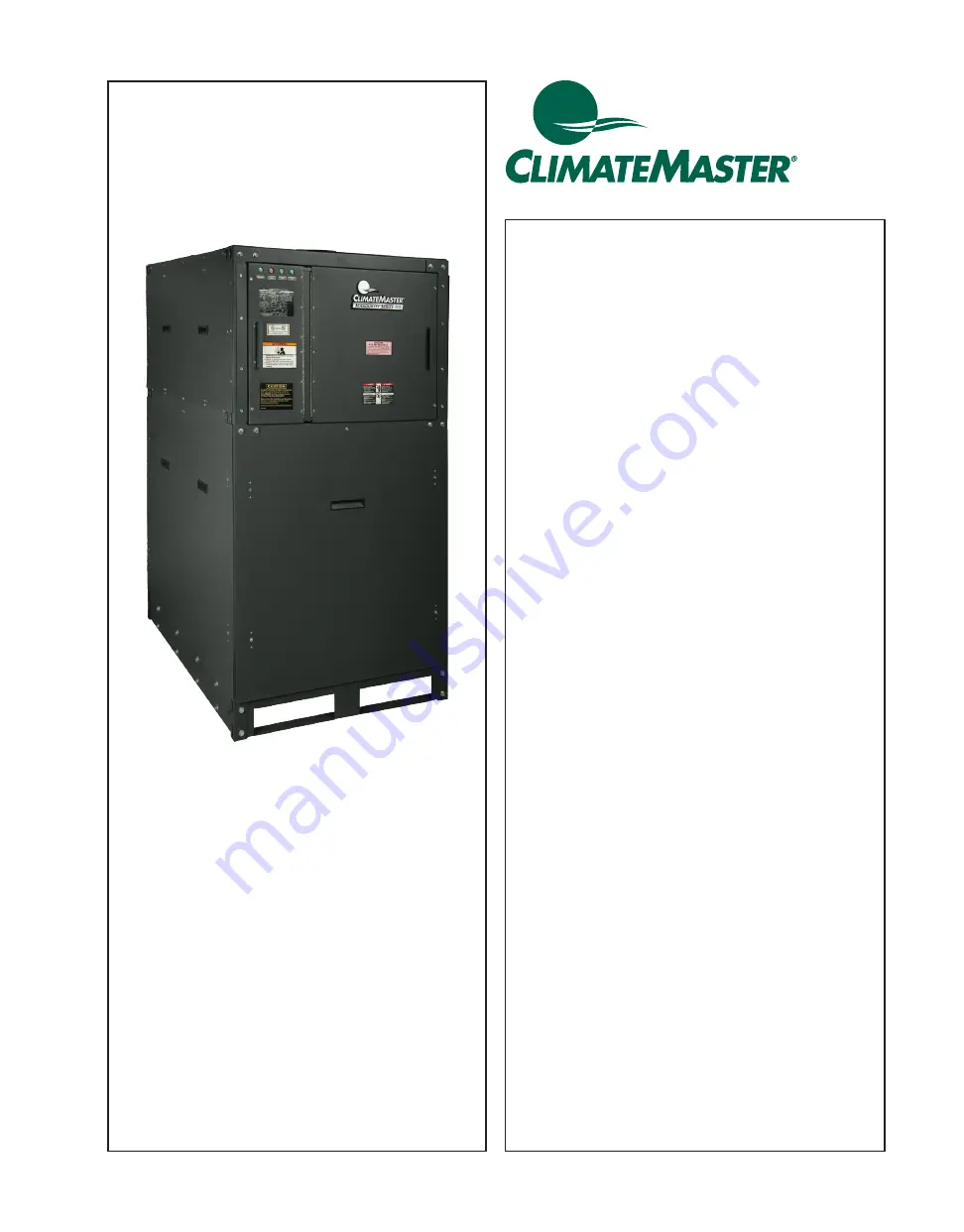
ClimateMaster TMW Series Installation Operation & Maintenance Download Page 1

Tranquility

®

 Large

Water-to-Water  

(TMW) Series

Models 360 - 840

Commercial  

EarthPure

®


Water-to-Water

Water-Source  

Heat  Pumps - 60Hz 

Installation, Operation  

& Maintenance

97B0090N01

Revised: October 5, 2021

Table of Contents

Model Nomenclature 

3

General Information 

4

Unit Physical Data 

6

Unit Dimensional Data 

7

Unit Installation 

8

Piping Installation 

9

Load Plumbing Installation 

10

Water Temperature Requirements 

10

Water-Loop Heat Pump Applications 

11

Ground-Water Heat Pump Applications 

12

Ground-Loop Heat Pump Applications 

13

Water Quality Standards 

14

Electrical - Line Voltage 

18

Wiring Diagram Matrix 

21

Typical Wiring Diagram 

22

Refrigeration Circuit Diagram 

25

Heat Exchangers 

26

Control System 

27

Control System Optional Features 

35

Control Sequence of Operation from BAS 

36

BACnet, Modbus, N2 Points List 

37

Unit Commissioning & Operating Conditions 

43

Piping System Cleaning & Flushing 

44

Pre-Start Up Procedures 

45

Pre Start-up Check List 

47

Unit Start Up Procedures 

48

Operation and Maintenance 

51

Operational Limitations 

53

Compressor Information 

54

Refrigeration System Recharging 

55

Sequence of Operation 

56

Factory Installed Options 

57

Field Installed Options 

57

Troubleshooting Guide 

58

Start Up Form 

59

Refrigeration Troubleshooting Form 

61

Warranty (US & Canada) 

62

Revision History 

64

Summary of Contents for TMW Series

Page 1: ...14 Electrical Line Voltage 18 Wiring Diagram Matrix 21 Typical Wiring Diagram 22 Refrigeration Circuit Diagram 25 Heat Exchangers 26 Control System 27 Control System Optional Features 35 Control Sequ...

Page 2: ...CL I MATEMASTER WATER SOURCE HEAT PUMPS Tranquility Large Water to Water TMW Series Rev Octob er 5 2021 ClimateMaster Water Source Heat Pumps 2 This Page Intentionally Left Blank...

Page 3: ...UMTEMPERATURE WATERTO WATER MODELTYPE UNIT SIZE 360 REVISION LEVEL C CURRENT VOLTAGE CONTROLS S SCROLL COMPRESSOR TYPE REFRIGERANT R REVERSE CYCLE HEATPUMP APPLICATION 0 NONE REFRIGERANT OPTIONS MODEL...

Page 4: ...hich is not hazard related WARNING All refrigerant discharged from this unit must be recovered WITHOUT EXCEPTION Technicians must follow industry accepted guidelines and all local state and federal st...

Page 5: ...ion Thoroughly check the system before operation Prepare units for installation as follows 1 Compare the electrical data on the unit nameplate with ordering and shipping information to verify that the...

Page 6: ...0 227 400 181 533 242 TMW840 557 252 565 255 452 204 601 271 Unit Corner Weights lbs kg Model TMW360 TMW600 TMW840 Compressor qty Scroll 2 Scroll 2 Scroll 2 Compressor Oil Type POE PVE PVE Factory Cha...

Page 7: ...BOTH SIDES NOTE 4 MINIMUM 2 1 2 ft 76cm REQUIRED SERVICE ACCESS 860 MINIMUM 18 REQUIRED SERVICE ACCESS HIGHVOLTAGE CONTROL BOX RV ACCESS PANEL LOWVOLTAGE CONTROL BOX HIGHVOLTAGE LOWVOLTAGE NOTE 1 DIM...

Page 8: ...codes and regulations ClimateMaster recommends locking down the TMW to a concrete base or to three 4 field supplied base rails that can support the unit weight Base pan has 6 bolt holes for securing t...

Page 9: ...corrosion resistant fittings and hoses and possibly water treatment Figure 1 Supply Return Hose Kit Figure 2 Connection Locations Insulation is not required on loop water piping except where the pipin...

Page 10: ...e performance and reduce nuissance to high pressure faults Figure 3 Load Water System Not all components of system shown See engineering specifications and drawings Note The manufacturer strongly reco...

Page 11: ...r connections commercial class to minimize internal fouling of the heat exchanger Do not overtighten connections and route piping so as not to interfere with service or maintenance access Hose kits ar...

Page 12: ...hat can be reduced by applying some back pressure This is accomplished by slightly closing the leaving isolation valve of the well water setup Shut off valves should be included for ease of servicing...

Page 13: ...ndency to corrode All plastic to metal threaded fittings should be avoided due to their potential to leak in earth coupled applications and a flanged fitting substituted P T plugs should be used so th...

Page 14: ...ing 0 0 0 0 L m s l l e c a i r e t c a B Sulfate reducing 0 0 0 0 L m s l l e c a i r e t c a b Suspended Solids 0 1 0 1 0 1 0 1 m p p S S T Earth Ground Resistance 0 s m h O Consult NEC local electr...

Page 15: ...hould not be used 7 If water temperature is expected to fall below 40 F antifreeze is required Refer to the heat pump IOM for the correct solution ratios to prevent freezing Hydrogen Sulfide has an od...

Page 16: ...e steel well casing The resistance measured should be zero Ohms The NEC allows a resistance to ground up to 20 Ohms Any resistance above zero indicates a poor earth ground which may be the result of a...

Page 17: ...be opera ng and the water stream owing The voltage measured should be less that 300mV 0 300 V If higher than 500mV electrolysis will occur and corrosion will result If voltage is measured the cause is...

Page 18: ...s of conductors Model Voltage Code Voltage Voltage Min Max Compressor Total Unit FLA Min Circuit Amps Max UL CSA HACR Qty RLA EA LRA EA TMW360 H 208 230 60 3 187 254 2 56 4 425 113 127 175 F 460 60 3...

Page 19: ...6 230 228 228v Next 100 228 226 0 9 228 The voltage imbalance of the three phase circuit is 0 9 This is well under the 2 range SAFETY WARNING WARNING High voltage is used to operate this equipment Fai...

Page 20: ...gize the compressor for a few seconds to ensure the discharge pressure gauge increases significantly If the discharge pressure does not increase proper rotation is reversed Compressor rotation can be...

Page 21: ...FOR ENERGY EFFI CI E N CY Wiring Diagram Matrix All diagrams can be located online at climatemaster com commercial literature wiring diagrams using the part numbers below Model Refrigerant Wiring Dia...

Page 22: ...CL I MATEMASTER WATER SOURCE HEAT PUMPS Tranquility Large Water to Water TMW Series Rev Octob er 5 2021 ClimateMaster Water Source Heat Pumps 22 Typical Wiring Diagram...

Page 23: ...climatemaster com 23 Tranquility Large Water to Water TMW Series Rev O ct ob er 5 2021 THE SMART SOLUTION FOR ENERGY EFFI CI E N CY Typical Wiring Diagram Cont d...

Page 24: ...CL I MATEMASTER WATER SOURCE HEAT PUMPS Tranquility Large Water to Water TMW Series Rev Octob er 5 2021 ClimateMaster Water Source Heat Pumps 24 Typical Wiring Diagram Cont d...

Page 25: ...INDICATOR 7 BI FLOW THERMAL EXPANSION VALVE 8 EVAPORATOR BPHX IN COOL MODE LOAD HX IN HEAT MODE SOURCE HX S1 DISCHARGE TEMPERATURE SENSOR S2 SUCTION TEMPERATURE SENSOR S3 ENTERING SOURCE WATER TEMP SE...

Page 26: ...opposite direction from the normal heat exchanger flow direction On the opposite service port connect a drain hose to run to a suitable floor drain Continue back flow until all debris is removed Chem...

Page 27: ...make sure the controller power is off The controller only reads the address when the unit is turned on The controller has two rotary switches for assigning the module s hardware address One switch co...

Page 28: ...lashes 4 Compressor 2 Out of Range Sensor 5 Flashes 5 Compressor No Run Alarm or Motorized Valve Alarm 6 Flashes 6 Hot Water Temperature Alarm 7 Flashes 7 Cold Water Temperature Alarm 8 Flashes 8 Load...

Page 29: ...This enables the user to access important information concerning setpoints active temperatures pressures operating modes alarm conditions unit scheduling servicing diagnostics and more See Figure 9 14...

Page 30: ...N m f a WMMMK ML p N e m f a WMMMK M p t l WMMMMKMc L i t l WMMMMKMc p Wr l c c L r j Wk c L m x m z x p b q r m z x e l j b z x i o j z i c E c k F j c k E MF _ k C f m c k E O F p p j c k E P F i o...

Page 31: ...K M c x m z x p b q r m z x e l j b z x i o j z q j t j p j i b t l p Wx MMMMK Mz c j b t l p Wx MMMMK Mz c j b t l p Wx MMMMK Mz c b t l p WMMMMK Mc x m z x p b q r m z x e l j b z x i o j z q j t i...

Page 32: ...MMz L Oa m W M MMM Np m W x MMMMz L Np m W MMMMKM Op m W x MMMMz L Op m W MMMMKM Na q W x MMMMKMz c L Na q W MMMMKM c Oa q W x MMMMKMz c L Oa q W MMMMKM c Np q W x MMMMKMz c L Np q W MMMMKMc Op q W x...

Page 33: ...ts a series of sub menus General System Settings Heating and Cooling Setpoint Menus Lead Compressor Rotation Setup Alarm Lockout Reset or FN 3 These variables are initially assigned a default value Fo...

Page 34: ...flow re established and a minimum pressure differential acknowledged by the differential pressure sensor The alarm clears automatically however the alarm condition is logged for permanent retention of...

Page 35: ...enu for Alarm Menu display or press FN 3 Compressor Thermal Protector Fault This would occur if the motor protector sensed an overload trip in the compressor motor It would also occur if any component...

Page 36: ...g and you will see the AV point AV 634 stg1_clg_pid_1 count up from 0 When the count reaches 50 the lead compressor will turn ON and when the count reaches 100 the lag compressor will turn ON B Heat P...

Page 37: ...lrm_1 Off BBI BI 7 1 06 Universal Input DEV 2460xx discrete in 10009 binary in 7 Source Cond Mot Valve AO 1 cnd_vlv_ao_1 4 80 BAO AO 1 0 01 Electrical 0 10 Volt DEV 2460xx float value 40051 analog out...

Page 38: ...x float value 40119 data float 34 Cool Mode Min Water Out Setpoint min_cool_load_stp_1 40 0 F BAV AV 87 DEV 2460xx float value 40417 data float 182 Heat Mode Outlet Water Setpoint 2 heat_temp_stp_1 12...

Page 39: ...0111 data float 28 Max Delta Temp Source 2 max_delta_temp_src_1 10 0 BAV AV 196 DEV 2460xx float value 40115 data float 29 Num 32 5 Ton Comps Req Stg1 num65t1req_1 0 0 BAV AV 197 DEV 2460xx float valu...

Page 40: ...Range comp2_oor_1 Off BBV BV 37 DEV 2460xx discrete in 10039 binary in 33 All Water Flows Status 2 flow_1 On BBV BV 38 DEV 2460xx discrete in 10045 binary in 39 Heat Mode Enable Input heat_enable_1 Of...

Page 41: ...Temp Alarm 5 cd_wtr_out_hi_alm_1 Normal BALM BV 97 DEV 2460xx discrete in 10100 binary in 94 Evap Water Outlet Hi Temp Alarm 5 ev_wtr_out_hi_alm_1 Normal BALM BV 98 DEV 2460xx discrete in 10101 binar...

Page 42: ...BV 196 DEV 2460xx discrete in 10085 binary in 79 Compr2 Low Suction Pressure Alarm 5 c2_low_suc_pres_alm_1 Off BALM BV 210 DEV 2460xx discrete in 10086 binary in 80 Compressor 2 Low Suction Superheat...

Page 43: ...wever usually no more than one of these factors may be at a minimum or maximum level at a time The commissioning table indicates water temperatures which are suitable for initial unit commissioning in...

Page 44: ...cement rate to equal the rate of bleed 7 Refill the system and add phosporic or sulfamic acid for a 2 solution If possible raise the Source loop temperature to approximately 100 F 38 C Circulate the s...

Page 45: ...cal diagram on the inside door of the electrical panel 6 Verify line voltage is within acceptable range see electrical table 4 DANGER Electric shock hazard May result in injury or death Disconnect pow...

Page 46: ...and blow out some water to check for particles or coloration from suspended particles Record the pressure differential across the load and source heat exchangers measured at the Pete s ports 8 Confirm...

Page 47: ...Source GPM s verified by pressure differential being provided to the unit 10 Is there water presently circulating through the unit 11 Is water within quality parameter table Refer to table 1 on page 1...

Page 48: ...anges to On and then press Enter or press the OK key Inside the low voltage control section left most control door turn the Compressor 1 switch ON to bump compressor 1 and check for proper rotation us...

Page 49: ...to varying installation conditions applications and to optimize performance proper refrigerant charge and TXV adjustment must be confirmed After checking compressor rotation choose a circuit to be te...

Page 50: ...ow or High High Low Turn TXV Adjustment Stem Clockwise Is Subcooling Low or High High Low Add Refrigerant Is Subcooling Low or High High Low Recheck Superheat and Complete Start up and Warranty Form A...

Page 51: ...drops across Load and Source heat exchangers Properly document all data taken The temperature drop rise on a fully loaded both compressors heat exchanger is generally 10 F If only one compressor is r...

Page 52: ...If correct water treatment has been implemented this should provide adequate cleaning for most situations The solution can be pumped through the heat exchangers and allowed to soak for a time and then...

Page 53: ...perheat at Compressor F 12 460 3 60 414 506 Maximum Oil Temperature Max F 200 575 3 60 518 632 Maximum Saturation Discharge Temperature F 145 Water Flow Data TMW360 TMW600 TMW840 Minimum Load Water Fl...

Page 54: ...ispense all refrigerant oil from sealed metal cans Oil Type Models POE TMW 360 TMW 600 REV A PVE TMW 600 REV B TMW 840 Oil Levels The oil level in the compressor should be checked with the compressor...

Page 55: ...moisture and contaminants from the refrigeration system After the initial vacuum is reached and held on the system allow dry nitrogen back into the system until the pressure reaches zero PSIG or sligh...

Page 56: ...protocol e g BACnet Modbus or N2 TMW will be disabled until Chilled Water Return CHWR temperature sensor is below 90 F and Source Water Supply SWS temperature sensor is above 60 F Each unit has 2 com...

Page 57: ...e CAUTION CAUTION CAUTION Prior to dismantling the strainer for cleaning it is imperative that the strainer assembly is isolated and completely de pressurized CAUTION Caution should be taken due to po...

Page 58: ...is 32 F the equivalent pressure setpoint will be 101 PSIG Compressor Cycles on High Pressure Control Possible Cause Remedy Main Source water valve closed or restricted Open valve to full open position...

Page 59: ...5 or less Verify Low Limit Low Pressure and High pressure safeties Compressor Operation Voltage Compressor Contactor during operation Warm Weather Operation Cooling Mode Cold Weather Operation Heating...

Page 60: ...t Up Form Cont d Water System Water Pipe Sizing Loop Type GPM Through Load Side F F GPM Through Source Side F F Cooling T Heating T Cooling T Heating T Antifreeze Type 60 Mesh Strainers Installed AFR...

Page 61: ...ting REFRIG FLOW HEATING REFRIG FLOW COOLING REFRIGERANT HFC 410A OPERATING MODE HEATING COOLING Source Load CIRCUIT 1 CIRCUIT 2 Description Heating Cooling Heating Cooling Notes Voltage Compressor Am...

Page 62: ...s a result of insuf cient or incorrect system design or the improper application of CM s products CM is not responsible for 1 The costs of any uids refrigerant or other system components or associated...

Page 63: ...climatemaster com 63 Tranquility Large Water to Water TMW Series Rev O ct ob er 5 2021 THE SMART SOLUTION FOR ENERGY EFFI CI E N CY Notes...

Page 64: ...l Removed LON Controls 10 01 21 Pgs 14 17 Updated Water Quality Standards 9 11 20 Pg 17 21 Updated Wiring Diagram Matrix All 3 Typical Wiring Diagrams and Refrigerant Circuit Diagram 8 11 20 Pg 21 23...

Reviews: