

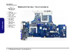


Disassembly
2 - 10 Removing the System Memory (RAM)
2.Disassembly
Removing the System Memory (RAM)
The computer has four memory sockets for 260 pin Small Outline Dual In-line Memory Modules (SO-DIMM) support-
ing DDR4 Up to 2400 MHz. The main memory can be expanded up to 64GB. The total memory size is automatically
detected by the POST routine once you turn on your computer.
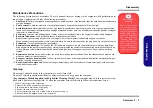
Memory Upgrade Process
6. RAM Shielding Plate
•
4 Screws
1.
Turn
off
the computer, turn it over, remove the keyboard (
) and battery (
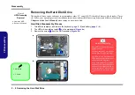
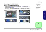
2.
The RAM-2 modules will be visible at point
on the mainboard (
)
.
3.
Gently pull the two release latches (
&
) on the sides of the memory socket in the direction indicated by the
arrows (
).
The RAM module
will pop-up
)
, and you can then remove it
.
4.
Pull the latches to release the second module if necessary.
5.
Insert a new module holding it at about a 30° angle and fit the connectors firmly into the memory slot.
6.
The module will only fit one way as defined by its pin alignment. Make sure the module is seated as far into the slot
as it will go. DO NOT FORCE IT; it should fit without much pressure.
7.
Press the module in and down towards the mainboard until the slot levers click into place to secure the module.
8.
Replace the bottom cover and the screws
(see
.
9.
Restart the computer to allow the BIOS to register the new memory configuration as it starts up.
1
2
3
4
b.
c.
3
3
2
2
1
a.
4
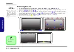
4. RAM Module
Figure 6
RAM Module
Removal
a. The RAM modules
will be visible at point
on the main-
board.
b. Pull the release lat-
ches.
c. Remove the module.
Contact Warning
Be careful not to touch
the metal pins on the
module’s connecting
edge. Even the clean-
est hands have oils
which can attract parti-
cles, and degrade the
module’s performance.
1
Summary of Contents for PA70HS
Page 1: ...PA70HS G PA71HS ...
Page 2: ......
Page 3: ...Preface I Preface Notebook Computer PA70HS G PA71HS Service Manual ...
Page 11: ...Preface IX Preface ...
Page 12: ...Preface X Preface ...
Page 26: ...Introduction 1 12 1 Introduction ...
Page 48: ...Disassembly 2 22 2 Disassembly ...
Page 51: ...Top A 3 A Part Lists Top Figure A 1 Top ...
Page 52: ...A 4 Bottom A Part Lists Bottom Figure A 2 Bottom ...
Page 53: ...Main Board A 5 A Part Lists Main Board Figure A 3 Main Board ...
Page 54: ...A 6 HDD A Part Lists HDD Figure A 4 HDD ...
Page 55: ...LCD A 7 A Part Lists LCD Figure A 5 LCD ...
Page 56: ...A 8 A Part Lists ...