background image


S-2R + Frontanbau 11.2018 en


Contents


Page 

1


Foreword ................................................................................................................................ 3


2


EC Declaration of Conformity .............................................................................................. 4


3


Introduction ........................................................................................................................... 5


3.1


General description and purpose of the device ................................................................ 5


3.2


Validity............................................................................................................................. 6


3.3


Contact ............................................................................................................................ 6


3.4


General technical data ..................................................................................................... 6


3.4.1


Machine number ...................................................................................................................... 6


3.4.2


Required equipment of the tractor ........................................................................................... 7


3.4.3


Attachment points to frames made by CLEMENS: .................................................................. 7


3.4.4


Technical data .......................................................................................................................... 7


4


Safety instructions ................................................................................................................ 7


4.1


General ........................................................................................................................... 7


4.2


Attached devices ............................................................................................................. 8


4.3


Road and transport journey ............................................................................................. 9


4.4


Maintenance and repair ................................................................................................... 9


4.5


Noise Information ............................................................................................................ 9


4.6


Hydraulic system, lubricants .......................................................................................... 10


4.7


Warning pictographs, nameplate ................................................................................... 11


5


First installation .................................................................................................................. 12


5.1


Attachment of the column lifter on the tractor................................................................. 12


5.2


Mounting of attachments to the column lifter.................................................................. 14


6


Putting into operation ......................................................................................................... 14


6.1


Road and transport journey ........................................................................................... 15


6.2


Operation and adjustment of the machine ..................................................................... 15


6.3


Removal from the tractor ............................................................................................... 15


7


Maintenance and replacement of wearing parts ............................................................... 15


8


Storage................................................................................................................................. 17


8.1


Before the season ......................................................................................................... 17


8.2


After the season ............................................................................................................ 17


9


Possible faults and their elimination ................................................................................. 17


9.1


Faults ............................................................................................................................ 18


9.2


Tightening torques ......................................................................................................... 18


10


Spare parts list .................................................................................................................... 19


10.1


Three-point frame for front mounting ............................................................................. 19


10.2


Link arms ....................................................................................................................... 20


10.3


Adapters and brackets for front mounting ...................................................................... 21


10.4


Accessories for mid-mounting ....................................................................................... 21


10.5


Column lifter S-2R ......................................................................................................... 22


10.6


Hydraulic cylinder .......................................................................................................... 24


10.7


Optional: Steel support wheel for mid mounting ............................................................. 25


10.8


Optional: Pneumatic support wheel for mid mounting .................................................... 26


11


List of illustrations .............................................................................................................. 28


Summary of Contents for CG866.300000

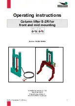
Page 1: ...2R Frontanbau 11 2018 en 1 Operating instructions Column lifter S 2R for front and mid mounting Item no CG866 300000 CLEMENS GmbH Co KG Maschinenfabrik Rudolf Diesel Stra e 8 D 54516 Wittlich Germany...

Page 2: ...Attachment of the column lifter on the tractor 12 5 2 Mounting of attachments to the column lifter 14 6 Putting into operation 14 6 1 Road and transport journey 15 6 2 Operation and adjustment of the...

Page 3: ...affic regulations serve your safety and the safety of third parties and must be followed In the course of further technical development CLEMENS GmbH Co KG is constantly working to improve its products...

Page 4: ...13857 2008 06 Agricultural Machinery Safety Part 1 General requirements DIN EN ISO 4254 1 2016 09 Agricultural Machinery Safety Part 5 Powered soil tillage implements DIN EN ISO 4254 5 2011 05 Fluid...

Page 5: ...aulic operation see note in chapter 10 5 The CLEMENS column lifter S 2R consists essentially of the following components Figure 1 General view column lifter S 2R Attention In this operating manual all...

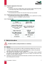
Page 6: ...49 0 65 71 929 192 Fax 530 661 0451 E Mail info clemens online com e mail thomas clemens america com Web www clemens online com 3 4 General technical data 3 4 1 Machine number For complaints and spare...

Page 7: ...hout accessories approx 120x420x920 mm approx 5 x17 x37 height adjustment 0 500 mm 0 20 max lifting load front for lateral mounting 600 kg 1322 lb 150 kg 330 lb lubricant sulfur free grease oil pressu...

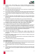
Page 8: ...illumination 15 If the device has to be lifted for mounting and dismounting as well as for maintenance and repair work sufficiently dimensioned and undamaged lifting gear must be used 16 Cranes and s...

Page 9: ...view Observe the respective regulations Germany 30 StVZO 13 Make sure that all implements are in the raised state when driving on the road 14 The horizontal distance between the frontmost part of fron...

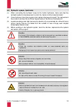
Page 10: ...n the hydraulic system lower the devices depressurize the system and switch off the engine Attention The hoses of the hydraulic cylinders must be renewed by a specialist workshop or the CLEMENS custom...

Page 11: ...pictographs nameplate Attention Hand protection Use durable chemical protective gloves for prolonged handling Apply skin protection cream to hands Avoid contact with skin Do not use solvents thinners...

Page 12: ...ds device to the wheel and from the RADIUS share to the rear wheel b Furthermore when mounting the RADIUS on the column lifter make sure that the support wheel is sufficiently far away from the unit t...

Page 13: ...justable in height It is important to ensure that when adjusting these plates always at least three holes match to ensure a secure connection to the base plate Screw on surfaces must be free of dirt a...

Page 14: ...he column lifter before starting work If a carrier frame is mounted its parking supports should be folded in or retracted and locked The hydraulic lines and wiring must be routed plugged in and secure...

Page 15: ...ic lines they should be depressurized In case of loose ground pay attention to the stability of the parked equipment In order to prevent overturning the support wheels should be equipped with wheel ch...

Page 16: ...a high pressure cleaner please ensure that the high pressure jet is not directed at bearings and sealing points or hydraulic connections This can lead to damage and premature failure Please use only s...

Page 17: ...ydraulic couplings should be covered by the supplied protective caps The storage place should be dry and protected from the weather The carrier frame to which the column lifter is attached should be p...

Page 18: ...l cylinder or replace if necessary bind oil Hydraulic oil shortage Check hydraulic oil level on tractor and top up if necessary Hydraulic oil filter clogged Check filter condition on tractor replace f...

Page 19: ...ax 530 661 0451 E Mail info clemens online com e mail thomas clemens america com Web www clemens online com 10 1 Three point frame for front mounting Figure 8 Spare parts three point frame for front m...

Page 20: ...head screw 2 093120070 1 6 Hexagon nut 2 093420 2 Hooked plate complete CA941 480200 2 1 Hooked plate 1 CA941 480210 2 2 Lock bolt 1 CW003 017200 2 3 Pipe locking pin 1 CW520 005100 2 4 Washer 4 01252...

Page 21: ...Order no not shown Device support complete for RADIUS MULTICLEAN 1 CL866 310000 1 Mounting tube 100 100 8 500 mm 20 1 CB866 304000 1 Mounting tube 100 100 8 800 mm 31 1 CD866 214000 2 Weld on flange...

Page 22: ...S 2R Frontanbau 11 2018 en 22 10 5 Column lifter S 2R Figure 16 Spare parts column lifter S 2R 8 3 9 14 6 2 10 8 8 7 4 1 12 15 11 16 9...

Page 23: ...00 2 Sliding element 1 CG866 302000 3 Hydraulic cylinder for details see 10 6 1 CF895 270000 4 Sealing plug 2 CW600 015400 6 Sticker CLEMENS 1 CW002 002300 7 Locking pin 1 CW003 011300 8 Washer 5 0125...

Page 24: ...k Quantity Order no 1 Piston rod 1 CB895 272000 2 Bushing 1 CL895 400001 3 Collar 1 CL895 400003 4 Guiding 1 CL895 400004 5 Collar 1 CL895 022003 6 Dust shield 1 CW780 003600 7 Piston seal 1 CW780 003...

Page 25: ...730000 4 Clamp complete 1 CA952 110000 5 Spacer disk large 1 CI903 700001 6 Spacer disk small 1 CI903 700002 7 Spacer ring 2 CI903 700003 8 Spacer ring large 2 CI903 700004 9 Lock washer M10 2 CW520...

Page 26: ...R Frontanbau 11 2018 en 26 10 8 Optional Pneumatic support wheel for mid mounting Figure 19 Spare parts pneumatic support wheel 9 3 4 7 1 10 14 15 11 11 6 16 13 6 17 18 12 2 9 9 5 19 20 21 23 24 24 25...

Page 27: ...010002 5 Axle galv 1 CW003 011700 6 Dust protection cover 2 CW004 002600 7 Clamp strap 1 CW030 000300 8 Toggle 1 CW031 000100 9 Lock washer 2 CW520 003400 10 Conical lubricating nipple 1 CW570 000100...

Page 28: ...point frame for front mounting 19 Figure 9 Spare parts Link arms 20 Figure 10 Mounting plate CL941 480400 21 Figure 11 Weld on plate CL866 301003 21 Figure 12 Mounting bracket Fendt Vario CO802 78700...

Reviews: