


PULSAR
®
IX SUCTION BLAST CABINET
Page 7
© 2019 CLEMCO INDUSTRIES CORP.
www.clemcoindustries.com
Manual No. 23425, Rev. C, 07/19
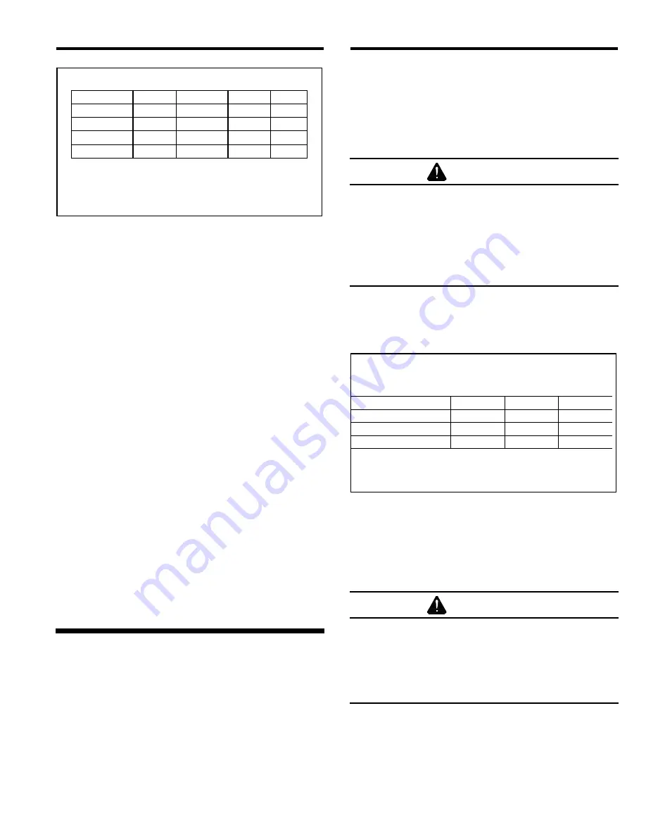
BNP
®
Gun
Jet
Nozzle
CFM
PSI
No. 4
1/8"
5/16"
21
80
No. 5
5/32"
5/16"
32
80
No. 6
3/16"
3/8"
47
80
* No. 7
7/32"
7/16"
62
80
* No. 8
1/4"
1/2"
86
80
Air Consumption in cfm
* Using this combination could affect usable media
size, refer to Section 1.9.
Figure 5
1.10.2
The air filter at the air inlet connection removes
condensed water from the compressed air. Its use is
especially important in areas of high humidity, or when
fine-mesh media are used. Moisture causes media to
clump and inhibits free flow through the feed assembly.
If the filter does not remove enough moisture to keep
media dry and flowing, it may be necessary to install an
air dryer or aftercooler in the air-supply line.
1.11
Electrical Requirements
1.11.1
Standard motor voltage is 230/460V, 3-PH. A
230-volt control panel is provided unless 460-volt is
specified at the time the order is placed. All wiring
external to the cabinet and power module is provided by
the user and must comply with local electrical codes. A
control panel is mounted on the power module; power
from the user's disconnect has to be wired to it. A 3-PH
control panel schematic and 115-V operator control
schematic is included and stowed in the control panel.
Additional wiring information is in Section 2.4.
1.11.2
NOTE: Full load amps (FLA) shown below are
for the motor only; the lights draw less than one amp.
Standard cabinets are supplied as follows:
900 cfm: 2 HP, 208/230/460V, 3-PH, 60 HZ
Supplied with 230-volt control panel unless 460-volt is
specified at the time the order is placed.
FLA 208/5.5, 230/5.6, 460/2.8.
2.0
INSTALLATION
2.1
General Installation Notes
2.1.1
Select a location where compressed air and
electrical service are available. The cabinet location
must comply with OSHA and local safety codes. Position
the cabinet and power module to allow for full access
around the operator station, all doors, service areas, and
for efficient handling of large parts. Ideally, the cabinet
and power module are positioned so the flex (conveying)
hose and blast hose are arranged with as few beds as
possible. Determine the best location for both modules,
and position them before final assembly.
2.2
Connect Compressed-Air Supply Line
WARNING
Failure to observe the following before
connecting the equipment to the compressed
air source could cause serious injury or death
from the sudden release of compressed air.
•
Lockout and tagout the compressed-air
supply.
•
Bleed the compressed-air supply line.
2.2.1
Refer to the table in Figure 6 to determine the
minimum ID of air-supply line to the cabinet. A smaller
diameter hose may reduce blasting efficiency.
Jet Size
Air Line Length
1/8"
No. 4
5/32"
No. 5
3/16"
No. 6
25 feet
3/4"
3/4"
1"
50 feet
3/4"
3/4"
1"
75 feet
3/4"
1"
1"
100 feet
3/4"
1"
1"
Minimum ID Compressed Air Line
Figure 6
2.2.2
Apply thread sealant to the male threads of an
air fitting that is compatible with the air-supply hose
fitting, as noted in Section 2.2.1, and
i
nstall it onto the
compressed-air filter located under the cabinet hopper
and shown in Figure 7.
WARNING
To avoid the risk of injury from compressed air,
install an isolation valve and bleed-off valve
where the air supply is tapped into the
compressed air system. Doing so enables
depressurization of the compressed-air line
before performing maintenance.
2.2.3
Install an isolation valve at the air source to
enable depressurization for service, and connect an air
line from the air source to the fitting installed on the air
filter.


