


750-297
Profire E/LNE Series Manual
4-3
Adjustments
4.4 — Gas System
4.4.1 — Gas Pressure
Gas must be supplied at a pressure high enough to overcome the pressure loss in the burner gas train and furnace
pressure while running at full input. Refer to nameplate inside control panel for gas pressure requirements at train inlet
and manifold. The pressures listed are based on nominal 1000 Btu/cu ft. natural gas at elevations up to 2000 feet above
sea level.
4.4.2 — Gas Flow
The volume of gas is measured in cubic feet as determined by a meter reading. The gas flow rate required depends on
the heating value (Btu/cu ft.). The supplying utility can provide this information as well as pressure correction factors.
To determine the required number of cubic feet per hour of gas, divide burner input (Btu/hr) by the heating value (Btu/
cu ft.).
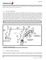
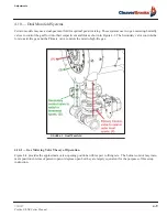
4.4.3 — Gas Pilot Flame Adjustment
The gas pilot flame is regulated by adjusting the pressure setting of the pilot regulator. Normal setting is 3" to 6" W.C.
when the pilot is burning. The flame must be sufficient to be proven by the flame detector and ignite the main flame.
Although it is possible to visibly adjust the size of the pilot flame, obtain a proper DC volt or microamp reading of the
flame signal.
The flame safeguard amplifier has a meter jack for this purpose. At initial startup and during planned maintenance, test
the pilot flame signal, pilot turndown, and safety switch lockout.
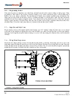
4.4.4 — Main Gas Pressure Regulator
The gas pressure required at the burner manifold is the pres- sure that is required to fire the burner at its rated capacity.
The gas pressure regulator must be adjusted to achieve this pressure to assure full input. Refer to manufacturer's
literature for regulator adjustment.
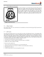
4.4.5 — Low Gas Pressure Switch
Turn adjusting screw until indicator moves to a pressure setting slightly below the operating gas pressure. The control
will break a circuit if pressure is below this set point. The control should be finally adjusted to prevent operation with
low gas pressure, but not at a pressure so close to normal operating pressure that unnecessary shutdowns occur. The
switch must be manually reset after tripping. To reset, allow gas pressure to rise and press the manual reset button.
NOTE:
When checking the input rate, Make sure no other equipment is operating on the same meter.
An ultra-violet flame sensor electrical spark interference test must be performed after final adjustment. See Section 4.3 of
this chapter for additional information.
!
Warning