18
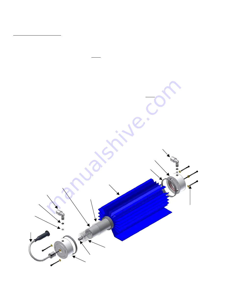
High Voltage End Cap
Brush Adapter Nut
High Voltage
Lead
Stainless Steel
Washer
Viton Washer
Oxygen Inlet Fitting
Contact Brush
High Voltage Anode
Glass Dielectric
Heat Sink and Cathode
Stainless Steel Clamp
Bottom End Cap
Ozone Outlet Fitting
End Cap Retaining
Screw and Washer
Step 10:
Inspect the dielectric, end caps and cathode for breakage, corrosion or debris. Clean and/or replace parts as
necessary. If cleaning and/or parts replacement is not required, re-assemble the reaction chamber per the
instructions below.
Assembly and Re-installation
Step 1:
Make sure the glass dielectric is clean (free of dust, dirt, grease, oils, etc.).
Step 2:
Prepare the end caps for re-assembly by replacing the O-rings. Thread the hex brush adapter nut, with contact
brush attached, onto the end of the high voltage end cap (cap with the white power lead attached) center screw.
Step 3:
Using a gentle twisting motion, press the
non
-high voltage end cap onto the heat sink/cathode assembly until
flush with the heat sink cooling fins.
Note: See Figure 8-2 for correct orientation of end cap.
Step 4:
Slide the four end cap retaining screws through the holes in the non-high voltage end cap, aligning them with
the heat sink screw bosses. Thread screws into screw bosses until heads are snug against the end cap.
Step 5:
Roll the high voltage anode (foil-like material) lengthwise, preserving the
longer
dimension. Insert the rolled
anode into the dielectric. Center the anode in the dielectric (approximately 1/2” from either end of the glass),
making sure it is rolled squarely.
Step 6:
Slide the dielectric into the heat sink/cathode assembly. Seat the dielectric into the O-rings of the non-high
voltage end cap by applying pressure with a gentle twisting motion. (There must not be any dirt, debris, oils or
fingerprints on the dielectric upon re-installation).
Step 7:
Slowly
insert the high voltage end cap assembly into the dielectric.
Note: Do not bend center wire of the
brush during this procedure.
It is normal for the
bristles
to bend. Using a gentle twisting motion, press the
high voltage end cap onto the heat sink/cathode assembly until flush with the heat sink cooling fins.
Step 8:
Slide the four end cap retaining screws through the holes in the end cap, aligning them with the heat sink screw
bosses. Thread screws into screw bosses until heads are snug against the end cap.
Step 9
:
Re-install complete reaction chamber assembly into the ozone generator by following the “Removal and
Disassembly” instructions in reverse order, from Step 6 to Step 2. Follow steps outlined in Chapter 7, “Start-
Up and Calibration,” to re-start the ozone system.
2” Pressurized Reaction Chamber - Exploded View
Figure 8-2


