143
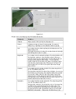
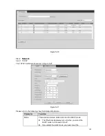
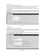
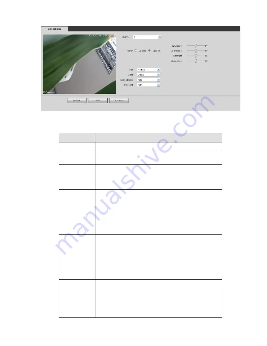
Figure 5-20
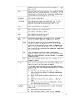
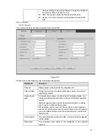
Please refer to the following sheet for detailed information.
Parameter
Function
Channel
Please select a channel from the dropdown list.
Period
It divides one day (24 hours) to two periods. You can set
different hue, brightness, and contrast for different periods.
Hue
It is to adjust monitor video brightness and darkness level. The
default value is 50.
The bigger the value is, the large the contrast between the bright
and dark section is and vice versa.
Brightness
It is to adjust monitor window brightness. The default value is 50.
The larger the number is , the bright the video is. When you
input the value here, the bright section and the dark section of
the video will be adjusted accordingly. You can use this
function when the whole video is too dark or too bright. Please
note the video may become hazy if the value is too high. The
value ranges from 0 to 100.The recommended value ranges
from 40 to 60.
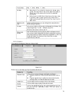
Contrast
It is to adjust monitor window contrast. The value ranges from 0
to 100. The default value is 50.
The larger the number is, the higher the contrast is. You can use
this function when the whole video bright is OK but the contrast
is not proper. Please note the video may become hazy if the
value is too low. If this value is too high, the dark section may
lack brightness while the bright section may over exposure .The
recommended value ranges from 40 to 60.
Saturation
It is to adjust monitor window saturation. The value ranges from
0 to 100. The default value is 50.
The larger the number is, the strong the color is. This value has
no effect on the general brightness of the whole video. The
video color may become too strong if the value is too high. For
the grey part of the video, the distortion may occur if the white
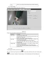
balance is not accurate. Please note the video may not be
Summary of Contents for PhoenixView 04B-04IP94
Page 1: ...Network Video Recorder User s Manual V 2 0 0 ...
Page 18: ...8 Select privacy mask zone ...
Page 79: ...69 Figure 4 81 Figure 4 82 ...
Page 80: ...70 Figure 4 83 Figure 4 84 ...
Page 86: ...76 Figure 4 89 Figure 4 90 ...
Page 87: ...77 Figure 4 91 Figure 4 92 ...
Page 88: ...78 Figure 4 93 Figure 4 94 ...
Page 90: ...80 Figure 4 96 Figure 4 97 ...
Page 177: ...167 The motion detect interface is shown as in Figure 5 54 Figure 5 54 Figure 5 55 ...
Page 178: ...168 Figure 5 56 Figure 5 57 Figure 5 58 ...
Page 182: ...172 Figure 5 62 Figure 5 63 ...


