background image

Gate

The XAP 400 has unique gating parameters which control microphone activation.

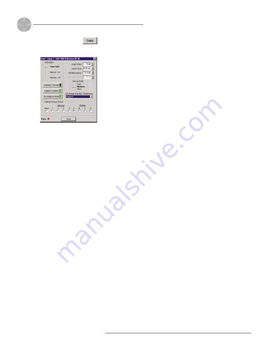
The Gate button on the selected input in Inputs 1–4 window opens the Gate

configuration window where you can establish the gating parameters for the input.

Activation

There are three mic activation settings: Auto Gate, Manual On, and Manual Off.

Auto Gate

determines mic gating based on the input level and gating settings

for the gating group the input is assigned to. It contributes to and is affected

by all gating group settings such as NOM, chairman override, etc.

Manual On

activates a mic, provided it does not exceed max NOM

requirements of the gating group that the input is assigned to. It is included in

the NOM count.

Manual Off

deactivates a mic.

Chairman Override

Chairman Override provides gating priority for this mic input over any other mic

input within the same gating control (mixer) groups. When a mic with Chairman

Override enabled gates on, all mics which don’t have Chairman Override enabled will

gate off. Default is off.

Adaptive Ambient

Adaptive Ambient adjusts the ambient reference level as noise and room conditions

change. When adaptive ambient is on, the mic channel monitors the ambient noise

level on the input and adjusts the ambient level reference automatically. This means

that the gate threshold level automatically increases or decreases based on back-

ground noise. If Adaptive Ambient is turned off, the input will use the fixed ambient

level specified in the Ambient Level box as its gating reference. Default is on.

PA Adaptive Mode

PA Adaptive Mode uses loudspeaker audio level on a specified output as the new

ambient level when audio is present at the power amplifier. This prevents

loudspeaker audio from gating on the mic, while still allowing people in the room to

gate on microphones as they speak—provided that their voices are louder than the

loudspeaker audio. For example, you might decide to play background music from a

CD player during a presentation. PA Adapt Mode allows you to use the output routed

from the CD player as the ambient reference to prevent the CD player’s audio from

gating on microphones. An output must be specified as the PA Adaptive Reference

(this is the same as the AEC reference) for each mic in the system. Default is on.

System Configuration

~ Inputs and Outputs

38

Technical Services Group ~ 1-800-283-5936 (USA) ~ 1-801-974-3760

Figure 3.35. Gate window

Summary of Contents for XAP 400

Page 1: ...Audio Products XAP 400 Audio Conferencing System Installation Operation Manual...

Page 2: ...XAP 400 Audio Conferencing System Installation Operation Manual...

Page 3: ...be reproduced in any form or by any means without written permission from ClearOne Communications Printed in the United States of America ClearOne Communications reserves specific privileges Informati...

Page 4: ...cking 3 Controls and Connections 4 Front panel 4 Rear panel 5 Networking 6 Expansion bus 6 Operational Requirements 7 Power 7 Telephone line 7 Equipment placement 8 Environmental 8 CHAPTER 2 Installat...

Page 5: ...Screen 27 Audio Routing 30 Expansion bus O Z routing 30 Process A D routing 30 Cross point attenuation 30 Matrix report 31 Inputs and outputs 32 Inputs 1 4 32 Inputs 5 8 44 Outputs 1 9 46 Expansion B...

Page 6: ...ace 72 To make and disconnect a call 72 To dial multiple numbers 72 To mute 72 Touch tone dialing 73 Utilities 74 Signal Generator 74 Document Compare Utility 75 Print Reports 78 Copy and paste settin...

Page 7: ...Serial commands 90 Command strings 91 APPENDICES 93 Appendix A Specifications 93 Appendix B Pinouts 95 Appendix C Control Panel 99 Appendix D Accessories 101 Appendix E Serial Commands 102 Appendix F...

Page 8: ...se such as that caused by fans or air conditioning Four independent processing blocks each with 15 filters delay and compressors provide pinpoint audio configuration Four mic line inputs four line inp...

Page 9: ...ech support clearone com Web site www clearone com Sales and Customer Service Telephone 1 800 945 7730 USA or 1 801 975 7200 Fax 1 800 933 5107 USA or 1 801 977 0087 E mail sales clearone com ClearOne...

Page 10: ...tion Product returns All product returns require a return authorization RA number Please contact ClearOne Technical Support before attempting to return your XAP 400 unit ClearOne is not responsible fo...

Page 11: ...sing channel of the XAP 400 The audio level of Output 8 is displayed by default See page 16 D Meter The Meter button takes you directly to the Meter branch of the XAP 400 s LCD programming tree See pa...

Page 12: ...800 PSR1212 units and 16 XAP TH2 units where the total number of microphone inputs does not exceed 64 The expansion bus supports a distance of up to 80 feet between each connected XAP 400 800 or PSR1...

Page 13: ...age 100 for maximum cable run distances when using ClearOne Control Panels Expansion bus The digital mix minus expansion bus RJ 45 LAN is used to connect up to eight XAP 800 400s and 16 XAP TH2 units...

Page 14: ...0 to be non compliant S Z buses These eight buses are defaulted as auxiliary mix buses They are used to route auxiliary audio such as from a CD player or VCR to and from other units on the network The...

Page 15: ...placement The XAP 400 models are designed for installation in a standard 19 inch equipment rack You can also purchase side panels for desktop placement See Appendix D for a list of accessories Environ...

Page 16: ...nitial connections creating an expansion bus E bus network assigning device ID numbers selecting the mixer mode and using the LCD menu The diagram below illustrates the typical connections that are ma...

Page 17: ...n down the top screw Inputs 1 4 B Mic or line level inputs Inputs 5 8 D Line level inputs only Outputs 1 8 C Line level outputs 6 If you are using a ClearOne Remote Panel wire it to the RS 485 port K...

Page 18: ...otal length between the XAP 400 and XAP 800 is 100 feet which is beyond the maximum 80 foot limit To create an expansion bus network 1 Plug the expansion bus terminator in the Expansion Bus In connect...

Page 19: ...audio from being received from units above the master unit in the network However global control of the system is still maintained by whichever XAP 400 800 or PSR1212 unit is connected to a control de...

Page 20: ...ring When power is applied to the XAP 400 the LCD panel will first read INITIALIZING If an error is displayed contact technical support When initialization is complete XAP 400 is displayed on the top...

Page 21: ...sed while a parameter is being adjusted the LCD will switch to the Meter menu System menu There are eight system level parameters see Figure 2 6 Select Preset Run Macro Lock Panel Set Passcode Device...

Page 22: ...Within a single site you must assign different device ID numbers for each XAP 400 unit See Device IDs page 12 Unit ID The Unit ID menu selection allows you to access the read only address set at the...

Page 23: ...em on power up and require a password before data transfer is allowed through the port When Off default is selected the password is disabled To use the XAP 400 with a modem 1 Match the baud rate of th...

Page 24: ...to monitor on the LCD and LED display Scroll to the output you want to monitor then press Enter ERL This submenu allows monitoring of the ERL meters on the XAP 400 Select the meter you want to monito...

Page 25: ...or From Telco Use the and buttons to select the Inputs menu then scroll through the options and press Enter when you reach the desired option Mute This submenu allows you to turn mute on or off defau...

Page 26: ...x Delay Compressor 15 Filters Assignable Processing All Pass Low Pass High Pass Low Shelving High Shelving 250mS Attenuation Mute M PEQ CD Horn Bessel Crossover Butterworth Linkwitz Riley Control Bus...

Page 27: ...20 Technical Services Group 1 800 283 5936 USA 1 801 974 3760...

Page 28: ...ts ClearOne s G Ware software provides an easy interface for configuring and controlling your XAP 400 While some configuration can be done using the front panel LCD menus G Ware is required to complet...

Page 29: ...ab and select G Ware If the Autorun window does not open open the Windows Start menu and choose Run Type drive gentner exe where drive is the letter of the CD ROM drive e g D gentner exe 2 At the G Wa...

Page 30: ...company location room and description using the Tab key or mouse to select each field 3 Click the Comm tab Select the COM port baud rate and flow control you want to use ClearOne recommends that you l...

Page 31: ...and place them in the Site pane See Figure 3 11 Note When connecting to your site you can choose to sync to Unit s or Document If you sync to the Unit s you will overwrite your G Ware site file with t...

Page 32: ...t Meter on the front panel meter LED when a channel is not specifically selected 5 Select the Meter Refresh Rate which determines how quickly the XAP 400 updates meter information default is 100ms ran...

Page 33: ...acro Editor Presets and Macros that are locked do not require the password to be run However the password is required to make changes 12 Select the Front Panel Lock Mode Unlock Panel leaves the front...

Page 34: ...you can access general configuration windows Unit specific configurations are accessed through the buttons and labels on the Flow Screen itself If you have multiple units click on the unit icon in th...

Page 35: ...ety Mute The Safety Mute feature in G Ware enables you to mute all outputs if feedback or audio problems occur during the configuration process To use Safety Mute click the Safety Mute button on the G...

Page 36: ...int cell identifies the input type yellow gated mic input blue non gated mic input and green all other inputs The amount of attenuation is also shown in the cross point cell Black cell are restricted...

Page 37: ...digital mix minus buses O R buses are defaulted as the mic mix buses and can communicate the NOM count Gated mics are default routed to the O bus S Z buses are defaulted as the auxiliary mix buses Th...

Page 38: ...the shortcut menu options To copy and paste a cross point to multiple cross points press Ctrl C to copy or right mouse click Then press Ctrl V while holding down the left mouse button and drag the mo...

Page 39: ...light gray The many configurable properties of mic inputs are defined in this section Mute Mute mutes the input channel The light on the button illuminates red when Mute is activated Default is Off un...

Page 40: ...ermines the decibel level at which you want the AGC to engage Setting the threshold toward the higher end of the scale near 0 reduces background noise to a greater degree The Response Time is measured...

Page 41: ...er will be able to reference both signals This means you don t need to use a dedicated output to combine signals Or you may have mics routed to the PA output but you don t want the echo canceller to r...

Page 42: ...ibels It is an average meter that updates only when a signal is present NC The NC button on the selected input in the Inputs 1 4 window opens the Noise Canceller window The noise canceller reduces amb...

Page 43: ...nter frequency range is 20Hz to 20kHz with resolution to 1Hz or four places whichever is larger Bandwidth is from 05 to 5 octaves in 01 octave increments Level is fixed at 80dB PEQ parametric equalize...

Page 44: ...node from the graph Table View Table View toggles between the Graph and the Table views of the Inputs 1 4 Filter window The Table view displays the selected filter settings in table format You can con...

Page 45: ...and room conditions change When adaptive ambient is on the mic channel monitors the ambient noise level on the input and adjusts the ambient level reference automatically This means that the gate thr...

Page 46: ...e is from 1 to 8 0 seconds Default is 3 seconds Off Attenuation Off Attenuation sets the amount of level reduction applied to a channel when it is gated off The range is from 0 to 50dB Default is 12dB...

Page 47: ...expansion bus output you want to use as the PA reference You can also open this window from the toolbar If you select a virtual echo cancellation reference point the Virtual Reference window will open...

Page 48: ...groups span two or more units global gating groups the settings must be the same for each unit attached to the global gating group Mic inputs are routed to Global Group A by default To assign a gating...

Page 49: ...s you to select which mic input the XAP 400 leave on when all mics gate off If Off is selected all mics will gate off when no audio is present It is preferable in most applications to leave a mic on s...

Page 50: ...ignal to noise ratio without clipping the signal Meters There are four meters on each mic line input to assist with setup and level control Select the meter check box to enable the meter All input met...

Page 51: ...ndow will open allowing you to rename the input The background color for the selected input channel will be light gray The configurable properties of these inputs are defined in this section Mute Mute...

Page 52: ...an input s gain directly affects sound quality The optimal input gain setting is one which is adjusted as high as possible above the noise floor without introducing clipping Clipping can cause distort...

Page 53: ...will open allowing you to rename the output The background color for the selected output channel will be light gray The configurable properties of these outputs are defined in this section Mute Mute m...

Page 54: ...nds absolute gain commands can exceed the min and max limits Min Max limits apply to all serially connected control devices and prevent users from adjusting levels beyond the min max levels provided r...

Page 55: ...ation and close the window To Expansion Bus O Z Click the To Expansion Bus O Z button on the Flow Screen to open the To Expansion Bus Labels window You can also access this window from the Matrix Scre...

Page 56: ...e mutes the processor The light on the button illuminates red when Mute is activated Default is off unmuted Cmprs compressor Cmprs opens the Compressor Setup window see Figure 3 54 With the compressor...

Page 57: ...requency range with no bass midrange or treble dropouts A given compressor group must be configured for a single XAP 400 unit a group cannot use compressors from multiple XAP 400 units Post Compressor...

Page 58: ...e Release determines how quickly compression is disabled The range is 100ms to 2 seconds in 5ms increments Default is 500ms Input meter This peak meter shows the level of the signal as it enters the c...

Page 59: ...ack their relationships to each other to design a system with the sound characteristics necessary for good audio Phase Phase plots the phase response of the frequency response of the selected filter B...

Page 60: ...ers Delay Click Delay to open the Delay configuration window Delay calibrates the amount of signal delay introduced based on the length the distance between the source and audience and temperature you...

Page 61: ...ain scale to create minimum and maximum gain level limits These limits only apply when using relative gain commands absolute gain commands can exceed the min and max limits Min Max limits apply to all...

Page 62: ...XAP 400 Flow Screen 2 The Telco Configuration window opens Adjust settings as necessary Refer to the table on the following page for a description of configurable settings 3 Click Close when you have...

Page 63: ...ing the signal to be boosted into a range where the hybrid can perform at an adequate level of acceptance Receive Boost can be turned on or off default This feature is set up during the initial config...

Page 64: ...or mics based on the number of mics gated on and routed to that output When using NOM over the expansion bus only the first four audio channels O P Q and R support passing NOM information Enable NOM i...

Page 65: ...n the signal for the telephone line only with no noticeable degradation in signal quality To use noise cancellation click Enable Noise Canceller then adjust the Cancellation Depth to the setting which...

Page 66: ...means you can change audio routing and configuration settings in a room without affecting settings in other rooms such as gain You can create up to 32 presets for the XAP 400 Presets can be executed i...

Page 67: ...with a cross point in the selected row will be saved Input rows that are not selected remain gray or masked and will not be affected when the preset is run Preset Configuration pane The Preset Config...

Page 68: ...g groups for this preset See page 41 for more information about gating groups Macro Selection The Macro Selection button opens the Preset Macros window where you assign specific macros to the preset y...

Page 69: ...ndard non preset Virtual Reference configuration you will need to select an output from the Output Level Tracking lists for each Virtual Reference you configure See page 34 for more information on cre...

Page 70: ...Click Gating Controls to set up gating parameters for the preset 6 Make GPIO or Remote assignments as needed 7 Click Virtual Reference if you need to create Virtual References specific to the preset 8...

Page 71: ...ries of commands which can be executed from G Ware or by using any external control device Typically you will create a macro for each configuration or group of presets you want to run at the same time...

Page 72: ...Room combining example In the room combining scenario depicted in Figure 4 10 there are four possible room configurations using six presets P1 P6 In order to change configurations without disturbing...

Page 73: ...s 0 so they can be run P4 runs and sets its state to on 1 which prevents other presets from reruning it P5 and P6 clear their states 0 so they can be run When the room is in Configuration 3 running th...

Page 74: ...your onscreen selections and the Macro Editor which allows you to directly create command lines The Macro Editor is also used to edit macros created using the Macro Recorder To create a macro using Ma...

Page 75: ...is the same as the preset password and is set in the Unit Properties window see page 26 4 Click Change Name to create a more descriptive name for the macro which is displayed in addition to the macro...

Page 76: ...om the Macro list 2 Click Change Name to edit the macro label 3 Double click the command line you want to edit The Current Line Number displays the selected command line 4 Make changes to the command...

Page 77: ...G Ware 1 Select the Run Macro button on the G Ware toolbar 2 Select the macro from the Select Macro list 3 Click Run to run the macro and close the window To run a macro using front panel control 1 F...

Page 78: ...green On LED D will light The red Off LED C will extinguish Upon connection the XAP 400 automatically adjusts to the line conditions Answer the call by picking up the telephone handset and talking to...

Page 79: ...numbers You do not need to click Dial 4 When you are finished with the call click Disconnect to end the call If there is noise on the phone line during a call you might need to click the Re Null butt...

Page 80: ...al one number at a time or a string of numbers Dial Dial activates when a number is entered in the In Block Dialing field Click it to Dial the number Speed Dial 10 numbers can be stored in Speed Dial...

Page 81: ...the operation of the processor settings you have selected To use pink or white noise 1 Select the XAP 400 Unit and Input Channel you want to use 2 Use the Amplitude control to select the amplitude vol...

Page 82: ...Repeat if you want Auto Sweep to continue in cycles 4 Click Signal On to generate the tone Click Signal On again to terminate the noise signal Document Compare Utility The Document Compare Utility sa...

Page 83: ...ically compares information from the selected items and displays a table of parameters which differ note that the actual differences are not displayed at this point This process can take a minute or t...

Page 84: ...on transfers the selected settings from a line selected in the Site 2 column to the corresponding line in the Site 1 column The Copy button copies the settings of the Site Line above it allowing you t...

Page 85: ...py of the settings you ve established for Inputs 1 4 Copy and paste settings In most areas of G Ware software right clicking the mouse opens a shortcut menu The options on this menu change depending o...

Page 86: ...Firmware Utility by clicking on the GFirm toolbar button 3 Click Browse to access a list of available firmware updates Select the file that matches the type of unit you are upgrading and click Open 4...

Page 87: ...ure The process begins by erasing flash sectors and then uploading the firmware file 8 If the process fails do not use the Start Over button Close GFirm instead and verify you are using a 9 pin straig...

Page 88: ...Ware and then G Ware Switcher The G Ware Switcher Utility Window opens G Ware Switcher automatically searches the PC for G Ware software versions and displays them in the window 2 Select the G Ware ve...

Page 89: ...y for units which have been added to G Ware The gate indicator for each input is dark green in the gate off condition and light green if the input is gated on Click Close to save the settings and exit...

Page 90: ...nges click Close to exit the window Telco meters Open the XAP 400 Telco Meters window by clicking the Telco Meters button on the Flow Screen The Telco Meters window is a diagnostic tool which allows y...

Page 91: ...he total echo return loss in the system The range of the meter is 50 to 0dB It is a peak meter and only updates when signal is present Transmit Input This meter shows the audio input level from the Ma...

Page 92: ...To program control status pins 1 Select the Control Status A pin you want to configure The current default pin assignment is displayed in the Active Low Inactive High Command box 2 Select the Device T...

Page 93: ...dial and dialing for a XAP system You can connect up to two XAP IR Remote Controls one to each RS 485 port See the XAP IR Remote user manual for more information The XAP IR Remote has five programmab...

Page 94: ...elect the Device Type ID and Command from their respective lists When you select a command a description of it appears in the Command Description box 8 Select the argument settings from the argument l...

Page 95: ...in list at the bottom of the window You can also set the upper and lower limits of gain on LEDs L2 and L8 and then click Auto Scale which automatically assigns values to LEDs L3 L7 on a distributed sc...

Page 96: ...Select an ID number for the remote from the Select Remote ID list 2 Click Change Name to create a more descriptive name limit 20 characters for the remote which is displayed in addition to the remote...

Page 97: ...the mode or upon power up of the unit You program the initialization string in Site Properties window in G Ware Typical configurations you set with the initialization string include setting a fixed ba...

Page 98: ...t locations The command string will support special characters See list at right To run a command string Use any external control device e g Control Panel GPIO control to run the STRING serial command...

Page 99: ...92 Technical Services Group 1 800 283 5936 USA 1 801 974 3760...

Page 100: ...Impedance 5k Nominal Level adjustable 55dBu 25dBu 0dBu Maximum Level 35dBu 5dBu 20dBu Echo Cancellation 130ms tail time works with 12dB of room gain Noise Cancellation 6 15dB attenuation Phantom Power...

Page 101: ...aptive Ambient on off Telco Line RJ 11 POTS plain old telephone service or analog extension from a PBX A lead supervision provided Telco Set RJ 11 Connect analog telephone set A lead supervision provi...

Page 102: ...n 9 Pin 6 Pin 1 XAP 400 Modem Pin 3 Pin 2 Pin 3 Pin 7 DB 9 Male DB 25 Female Pin 5 Pin 2 AMX XAP 400 TXD Pin 2 RXD Pin 3 GND Pin 5 RX2 White TX2 Red GND Black DB 9 Female Phoenix Connectors CTS Pin 7...

Page 103: ...ate Status 23 No S Mic 7 Gate Status 24 No S Mic 8 Gate Status 25 No Ground Ground 13 25 1 14 Figure B 6 Control Status Ports A B Control Status connectors The Control Status connections are provided...

Page 104: ...Pin 7 9 No C Preset select bit 10 No S Preset select status for Pin 9 11 No C Preset select bit 12 No S Preset select status for Pin 11 13 No C Preset select bit 14 No S Preset select status for Pin 1...

Page 105: ...5 of SET 5 To pin 2 of LINE 3 Ring 6 To pin 1 of LINE RJ 11C Line connector pinout Pin Description Pin Description 1 To pin 6 of LINE RJ 11C 4 Ring 2 To pin 5 of LINE 5 To pin 2 of SET 3 Tip 6 To pin...

Page 106: ...screws and an electrical wall box shown in Figures C 5 and C 6 If any parts are missing please contact ClearOne 2 Using DIP switches 1 4 assign a unique ID to the Control Panel Refer to Figure C 2 for...

Page 107: ...Figures C 5 and C 6 use the supplied pan head screws to install the Control Panel PCB assembly to the electrical wall box 9 To install the facia plate position it over the conductive rubber switch pad...

Page 108: ...051 FACIA PLATE 915 155 051 ASSEMBLY VOLUME CONTROL PANEL INCLUDES 820 155 051 VOLUME CONTROL PANEL PCB ASSEMBLY W TWO FOUR PIN PHOENIX CONNECTORS 740 155 052 CONTROL PANEL MOUNTING BRACKET 625 100 0...

Page 109: ...ce type character and a device number The device type for the XAP 400 is always 7 and the device ID will always be 0 7 or to select all 400 units Command structure Commands can be either UPPER CASE or...

Page 110: ...ll channels For example a group value of M and a channel value of would mean that the command is to be applied to all channels of group M mic inputs The following table shows the alpha representations...

Page 111: ...The command dictionary needs to be updated 4 Not implemented The command is not implemented 5 Argument error The command had an argument that was out of range 6 Unknown command The command is unknown...

Page 112: ...ain for in out or process Command Function GATE Reports gate status of channels 1 4 GHOLD Selects reports hold time setting GMODE Selects reports gating mode setting GOVER Selects reports gating overr...

Page 113: ...PA adapt mode for mic outputs REFSET Selects reports the output the reference channel tracks Command Function RING Indicates a ringing line reportable only RINGER Sets the audible ringer for a telco...

Page 114: ...form DEVICE AAMB Channel Group Value Argument details Name Description Device 0 7 or to select all units AAMB Command form Channel Range 1 4 Selects input Group M Selects mic group Value 0 Off 1 On 2...

Page 115: ...setting of auto disconnect Command form DEVICE AD Channel Value Argument details Name Description Device 0 7 or to select all units AD Command form Channel See Groups and Channels on page 103 Value 0...

Page 116: ...M channel 1 is set to off 0 AGCSET Automatic Gain Control Adjust This command selects reports the settings of the AGC on the input channels Command form DEVICE AGCSET Channel Group Threshold Target At...

Page 117: ...This command selects reports the setting of the ambient level Command form DEVICE AMBLVL Channel Value Argument details Name Description Device 0 7 or to select all units AMBLVL Command form Channel...

Page 118: ...ompressor group 1 2 compressor group 2 3 compressor group 3 4 compressor group 4 null to return the current mode Example 72 CGROUP A 2 On XAP 400 unit 2 72 the compression group CGROUP for processing...

Page 119: ...e 100 to 2000 select in 5ms intervals ms Gain 0 00 to 20 00 dB Example 71 COMPRESS A 6 5 25 250 3 On XAP 400 unit 1 71 the compression COMPRESS within processing channel A is set to have a threshold o...

Page 120: ...ay rate for a specified input Command form DEVICE DECAY Channel Value Argument details Name Description Device 0 7 or to select all units DECAY Command form Channel Range 1 4 selects mic input Value 1...

Page 121: ...Command form DEVICE DFLTM Channel Group Position Argument details Name Description Device 0 7 or to select all units DFLTM Command form Channel 1 8 Group I Inputs O Outputs M Mic Inputs L Line Inputs...

Page 122: ...rsion is a date and time stamp This command is read only Command form DEVICE DSPVER value Argument details Name Description Device 0 7 or to select all units DSPVER Command form Value Null Example 75...

Page 123: ...cy Gain Bandwidth Argument details Name Description Device 0 7 or to select all units FILTER Command form Channel See Groups and Channels page 103 Group See Groups and Channels page 103 Node 1 4 selec...

Page 124: ...s on and off the filters on input and audio processing channels Command form DEVICE FILTSEL Channel Group Node Value Argument details Name Description Device 0 7 or to select all units FILTSEL Command...

Page 125: ...and sets and reports the current passcode setting for the unit Each character in the password represents a button on the front panel See button assignment table below When the user is requested to unl...

Page 126: ...and reports the gate status of mics This command is read only Command form DEVICE GATE Argument details Name Description Device 0 7 or to select all units GATE Command form The command will return the...

Page 127: ...lects reports the setting of gating mode Command form DEVICE GMODE Channel Value Argument details Name Description Device 0 7 or to select all units GMODE Command form Channel 1 4 select mic input Val...

Page 128: ...GREPORT Value Argument details Name Description Device 0 7 or to select all units GREPORT Command form Value 0 Off 1 On 2 Toggle Example 73 GREPORT 1 On XAP 400 unit 3 73 the gate reporting GREPORT is...

Page 129: ...select all units HOOK Command form Channel See Groups and Channels page 103 Value 50 to 2000 ms Null to query in text Example 76 HOOKD 1 500 On XAP 400 unit 6 76 the hook flash duration HOOKD for the...

Page 130: ...units LMO Command form Channel See Groups and Channels page 103 Value 0 Last Mic Mode disabled 1 8 Select Last Mic mode on specified channel Last mic to stay on Null to return the current mode Exampl...

Page 131: ...Selects reports the password for the preset macro lock This can only be changed if unit is unlocked Command form DEVICE LOCKPWD Value Argument details Name Description Device 0 7 or to select all uni...

Page 132: ...On Add specified level to list of levels to be reported 2 Toggle Example 72 LVLREPORT 8 L I 1 On XAP 400 unit 2 72 the level LVLREPORT of line level L input 8 at the input stage I is to be added 1 to...

Page 133: ...vice 0 7 or to select all units MASTER Command form Value 1 Master 2 Slave Null Current mode of the unit Example 76 MASTER 2 On XAP 400 unit 6 76 the MASTER mode is set to slave 2 MAX Maximum Gain Set...

Page 134: ...ame Description Device 0 7 or to select all units MDMODE Command form Value 0 Off 1 On 2 Toggle Null current modem mode state Example 77 MDMODE 1 On XAP 400 unit 7 77 the modem mode MDMODE is on 1 MIN...

Page 135: ...g Null Current string Example 76 MINIT ATZ On XAP 400 unit 6 76 the modem initialization string MINIT is ATZ MINMAX Minimum and Maximum Gain Setting This command changes or reports back the minimum an...

Page 136: ...and form Channel 1 4 mic inputs A D gating groups Value 0 Unlimited 1 8 Maximum number of mics Null Current maximum number of microphones Example 72 MMAX A 4 On the XAP 400 unit 2 72 the max number of...

Page 137: ...nnel 1 is routed MTRX as gated 4 to output O 4 MTRXLVL Matrix Attenuation Adjustment This command selects reports the matrix level at the cross point Command form DEVICE MTRXLVL SRC CHNL SRC GRP DEST...

Page 138: ...ent details Name Description Device 0 7 or to select all units NCD Command form Channel 1 4 select mic input or 1 telco receive Group M or R Value 6 15 set noise cancellation from 6 to 15dB Null to re...

Page 139: ...es Mode This command selects reports the setting of Number of Open Microphones NOM on output channels Command form DEVICE NOM Channel Value Argument details Name Description Device 0 7 or to select al...

Page 140: ...command selects reports PA adaptive mode for the specified mixer There can be only one selection per mixer Command form DEVICE PAA Channel Value Argument details Name Description Units Device 0 7 or...

Page 141: ...to off Null Returns the current preset state Example 72 PRESET 5 1 On XAP 400 unit 2 72 preset PRESET 5 will execute and set the state to on 1 PRGSTRING Program String This command sets reports a pro...

Page 142: ...0 the ramp will stop If value 0 the gain will ramp down If value 0 the gain will ramp up Target 65 to 20 dB If null in text the ramp will use the channel s maximum and minimum for a target Example 77...

Page 143: ...eference REFSEL for mic channel 1 is output O 12 REFSET Reference channel setup This command selects reports the output the reference channel tracks Command form DEVICE REFSET Channel Group Value Argu...

Page 144: ...ts the audible ring level Command form DEVICE RINGERLVL Channel Value Argument details Name Description Units Device 0 7 or to select all units RINGERLVL Command Channel See Groups and Channels page 1...

Page 145: ...ects reports the status of the Telco receive reduction Command form DEVICE RXRD Channel Value Argument details Name Description Device 0 7 or to select all units RXRD Command Channel See Groups and Ch...

Page 146: ...all units SFTYMUTE Command Value 0 Off 1 On 2 Toggle Null Current state Example 72 SFTYMUTE 1 On XAP 400 unit 2 72 safety mute SFTYMUTE is enabled 1 SIGGEN Signal Generator This command selects repor...

Page 147: ...eports the setting of speech level control for a microphone Command form DEVICE SLVL Channel Value Argument details Name Description Device 0 7 or to select all units SLVL Command Channel 1 4 select m...

Page 148: ...G String Execution This command sends the specified string out the serial port Command form DEVICE STRING ID Argument details Name Description Device 0 7 or to select all units STRING Command ID 0 7 N...

Page 149: ...ad only Command form DEVICE TERL Channel Value Argument details Name Description Units Device 0 7 or to select all units TERL Command Channel See Groups and Channels page 103 Value Null to return TERL...

Page 150: ...out TOUT after 5 minutes UID Unit ID This command reports the unit ID This command is read only Command form DEVICE UID Value Argument details Name Description Units Device 0 7 or to select all units...

Page 151: ...ARRANTY IS VOID IF A The product has been damaged by negligence accident act of God or mishandling or has not been operated in accordance with the procedures described in the operating and technical i...

Page 152: ...th below in writing giving full particulars as to the defects or unsatisfactory operation Upon receipt of such notice the Manufacturer will give instructions respecting the shipment of the product or...

Page 153: ...rea is likely to cause harmful interference in which case the user will be required to correct the interference at his her own expense Changes or modifications not expressly approved by ClearOne Commu...

Page 154: ...arts are contained in this product If damage or malfunction occurs contact ClearOne Communications for instructions on its repair or return This equipment cannot be used on telephone company provided...

Page 155: ...e appropriate electrical inspection authority or electrician as appropriate European Compliance This equipment has been approved in accordance with Council Directive 1999 5 EC Radio Equipment and Tele...

Page 156: ...ods of measurement EN 61000 4 2 1995 A1 1998 Electrostatic Discharge EN 61000 4 3 1996 A1 1998 Radiated RF Immunity EN 61000 4 4 1995 Electrical Fast Transients EN 61000 4 5 1995 Lightning Surge EN 61...

Page 157: ...Attenuation A reduction of signal amplitude Audible Hook Indication The unit signals when it goes on or off hook with a series of beeps This indication can be turned on or off in the Telco Configurat...

Page 158: ...drivers Compression An induced reduction in the dynamic range of part or all of an audio signal Compression is usually used to protect individual loudspeaker components from the damaging effects of t...

Page 159: ...ere Delay A setting in the Processing window Delay calculates the amount of signal delay up to 250ms based on the distance between audio source and audience and the temperature Device ID A number whic...

Page 160: ...user definable requirements of the system All Pass A filter that provides only phase shift or phase delay without appreciably changing the magnitude characteristic The filter produces a flat amplitude...

Page 161: ...ill gate on according to the input level assigned gating parmeters and gating group Manual On The microphone will gate on unless it exceeds the NOM requirements of the gating group Manual Off The micr...

Page 162: ...es the routing of any input to any output or combination of outputs Maximum Number of Mics Sets the maximum number of mics that can be gated on simultaneously Microphone Activation A condition in whic...

Page 163: ...hone while still allowing people in the room to gate on microphones as they speak PA Adapt AEC Reference This G Ware setting determines which output typically for a loudspeaker is used as a reference...

Page 164: ...AP 400 A preset can be programmed with a variety of routing level gating delay filter and equalizer settings to meet specific application requirements Preset Mask Defines whether a contact closure act...

Page 165: ...alization of the source even with a distributed system Signal Generator A device for generating a reference tone for sound system calibration purposes Site file A site file is a file created by G Ware...

Page 166: ...s The Unit Properties window opens when you add a new unit to the site It allows you to enter information about the unit as well as configure the communication and security settings Virtual reference...

Page 167: ...58 105 110 150 auxiliary audio 7 30 33 44 151 158 B bandwidth 36 37 116 117 151 156 157 baud rate 16 23 25 90 93 105 110 151 C call progression 56 category five twisted pair cable 11 Chairman Override...

Page 168: ...passcode 15 G G Ware 22 installation 22 Program Folder 22 G Ware Switcher 81 gain structure 43 45 47 54 154 Gate 6 7 38 activation 38 adaptive ambient 38 ambient level 39 auto gate 38 chairman overrid...

Page 169: ...ocessing 17 Telco RX 17 Telco TX 17 TERL 17 TERLE 18 Meter reference 19 Meter View 82 Meters 43 post gain 43 post gating 43 post processing 43 pre pain 43 Min Max limits 42 mixer mode 9 12 14 15 155 m...

Page 170: ...2 73 receive ALC 56 receive boost 56 Receive Input 84 Receive Output 84 receive reduction 56 release time 112 158 Remote Builder 27 61 85 86 87 Remote Panel 6 10 64 86 98 99 100 response time 33 109 s...

Page 171: ...n 58 Mute 58 NC 58 TERL 16 17 83 84 106 142 159 TERLE 16 18 83 106 142 159 threshold 33 38 39 49 51 94 109 112 Tone 74 touch tone 73 Transmit Input 83 Transmit Output 83 U Unit Properties 25 26 60 68...

Page 172: ...165 Technical Services Group 1 800 283 5936 USA 1 801 974 3760...

Page 173: ......

Reviews: