Clear-Com RCV-2 Instruction Manual Download Page 8

W i r e l e s s   I F B / C u e   S y s t e m

2 - 2

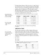
with another transmitter strip to allow operation on a different frequency. The 
transmitter is available set to any of over 1,600 different frequencies between 169 
MHz and 216 MHz. This frequency must be pre-set at the factory. It is not field 
adjustable. Consult your dealer or the Clear-Com factory for details on 
frequency coordination and changes.

A 1/4-wave “whip” antenna is provided with the UPX-10. Other antennas, such 
as the Clear-Com Model 123U dipole antenna may be used to facilitate rack 
installation or to improve coverage where the standard whip antenna would 
otherwise be blocked or shielded by equipment cabinets or large objects.

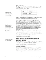
RCV-2 WIRELESS BELTPACK RECEIVER 
(MODELS RCV-2, RCV-2S, RCV-2D)

The Clear-Com RCV-2 wireless receiver is a miniature portable device normally 
worn on the body of the user. Small and lightweight, it operates from a single 
9-volt battery for 8-10 hours of operation. It features a low-battery indicator and 
rechareable battery operation. It is useful for a variety of one-way personal 
communications purposes.

The RCV-2 operates in the high-band VHF frequency range of 169 to 216 
MHz. Systems employing the RCV-2 require licensing under FCC Part 90 or 
Part 74. It is compatible with the Clear-Com UPX-10 and WBS-6/600 
transmitters.

Note

: Any change or modification made to this product without the express written 

authorization and approval from Clear-Com could void the user’s authority to operate 
this equipment. 

The RCV-2 may be ordered with either one or two frequencies installed, and is 
switchable between those frequencies for maximum flexibility.   

OPERATION

UPX-10 TRANSMITTER

The UPX-10 transmitter is intended to be used only with the Clear-Com RCV-2 
wireless beltpack receiver (Models RCV-2, RCV-2S, and RCV-2D). The UPX-10 
transmitter is not compatible with receivers from other manufacturers.

Frequency Selection

You must choose a transmit frequency for the UPX-10 that can coexist with 
other RF systems in the coverage area. This frequency must be specified at the 
time of purchase. The Clear-Com factory provides a frequency coordination 
service free of charge for this purpose.

Note:

 There are restrictions on the use of specific frequency ranges by certain types of 

users. If you do not understand these restrictions or are uncertain of their applicability, 
consult your Clear-Com dealer or the Clear-Com factory.

NOTE

: The UPX-10 

transmitter is not 

compatible with receivers 

from other 

manufacturers.

• The  RCV-2  wireless 

beltpack receiver may be 

ordered with either one 

or two frequencies 

installed.

• Clear-Com provides a free 

frequency coordination 

service. 

Summary of Contents for RCV-2

Page 1: ...UPX 10 TRANSMITTER I N S T R U C T I O N M A N U A L WIRELESS IFB CUE SYSTEM RCV 2 RECEIVER...

Page 2: ...rved Part Number 810179 Rev D Clear Com Intercom Systems 4065 Hollis Street Emeryville CA 94608 3505 U S A Clear Com is a registered trademark of Clear Com Intercom Systems The Clear Com Logo is a reg...

Page 3: ...taching the Antenna 3 1 Connecting the System 3 2 Adjusting the Settings 3 3 Initial Settings 3 3 Audio Level Setting 3 4 Audio Frequency Response and Dynamic Range Adjustments 3 4 Installing the Clea...

Page 4: ...W i r e l e s s I F B C u e S y s t e m...

Page 5: ...ith an audio input applied to the unit adjust the front panel input level adjust control until the audio level bargraph meter indicates peaks in the 0 to 2 VU range 7 Attach the earpiece or headset to...

Page 6: ...W i r e l e s s I F B C u e S y s t e m...

Page 7: ...adjusting the low and high frequencies are located on the rear panel In addition the audio dynamic range can be limited by either a 2 1 logarithmic compressor or by a wide range Automatic Level Contro...

Page 8: ...Part 90 or Part 74 It is compatible with the Clear Com UPX 10 and WBS 6 600 transmitters Note Any change or modification made to this product without the express written authorization and approval fr...

Page 9: ...s the RCV 2 to be recharged without removing the battery and without disconnecting or dissassembling the headset Antenna The RCV 2 receiver uses the headset or earpiece cable as the antenna For best p...

Page 10: ...W i r e l e s s I F B C u e S y s t e m 2 4...

Page 11: ...chable rack mounted ears must first be installed on the UPX 10 as follows 1 Loosen but do not remove the four screws on the two sides of the unit that hold the top cover onto the chassis 2 Slide the t...

Page 12: ...UPX 10 through the XLR connector located on the rear panel The base station comes with the internal jumpers programmed for use with a Clear Com intercom system The pin assignments are consistent with...

Page 13: ...operation ADJUSTING THE SETTINGS There are no user serviceable adjustments located inside the UPX 10 In addition normal setup and operation does not require internal access Refer all service and inter...

Page 14: ...mic range setting is selected it will be necessary to readjust the variable audio level control to achieve the O VU reading on the front panel bargraph If the VU meter consistently reads higher than O...

Page 15: ...a two channel unit RCV 2D Select the desired frequency by sliding the switch on the receiver top panel to 1 or 2 as appropriate The frequency of the RCV 2 receiver must match the frequency of the tran...

Page 16: ...permanent effects including hearing loss The use of low impedance 8 to 20 Ohms and high efficiency headsets and earpieces with the RCV 2 should be limited to those with existing hearing impairments A...

Page 17: ...eplacing the battery with a fresh unit in the event of any sort of problem with the system because a low battery may affect system operation in subtle ways When you turn off the power to the UPX 10 tr...

Page 18: ...ese include furniture lighting fixtures scaffolding electrical cables metal structural members aluminum window frames and equipment cabinets Whip and dipole antennas require at least 5 inches 12 7 cm...

Page 19: ...Rear panel mounted slide switch Audio Input Level Line 10 to 20 dBu Mic 40 to 10 dBu Audio Input Adjust Range 30 dB Audio Frequency Compensation Low 10 dB High 10 dB Front Panel Controls and Indicato...

Page 20: ...ortion 1 typical 1 kHz Signal to Noise Ratio 78 dB minimum Audio Output 100 milliwatts minimum into 8 Ohms Power 9 volt battery accepts 9 2 to 6 3 VDC Current Drain 40 milliamps max with 10 milliwatt...

Page 21: ...e implied warranty of merchantability are limited to the duration of this express limited warranty Neither Clear Com nor the dealer who sells Clear Com products is liable for incidental or consequenti...

Page 22: ...ized service facilities If requested an estimate of repair costs will be issued prior to service Once repair is approved and repair of equipment is completed the equipment will be shipped freight coll...

Page 23: ...I M F 1 0 2 I N T E R F A C E M O D U L E F R A M E 6 3 NOTES...

Page 24: ...I M F 1 0 2 I N T E R F A C E M O D U L E F R A M E 6 4 NOTES...

Reviews: