


W i r e l e s s I F B / C u e S y s t e m
3 - 2
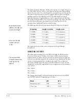
For optimum antenna efficiency, the whip wire may be cut to length. Do
not
try
to cut the whip with wire cutters, as the whip is made from steel and will likely
destroy the wire cutters. Use a bench grinder or equivalent to grind through the
whip wire, being careful to use protective goggles and heavy gloves during the
grinding operation. The following chart lists the ideal lengths for various
operating frequencies. Lengths shown are for the exposed portion of the whip.
The actual cut length will be 0.175 inch (0.45 cm) longer. The values also differ
from the theoretical quarter wavelength due to the loading effects of the
connector barrel and the ball on the end of the whip.
The following table shows the approximate length of whip versus frequency:
For frequencies between chart entries, determine the length through
interpolation.
CONNECTING THE SYSTEM
The audio signal is transmitted to the UPX-10 through the XLR connector
located on the rear panel. The base station comes with the internal jumpers
programmed for use with a Clear-Com intercom system. The pin assignments
are consistent with that required by the intercom system. Alternatively, the base
station can be programmed for a standard audio signal. This is a balanced,
transformer-isolated input. The input is also DC isolated to 50 volts. For the
standard mic- or line-level input modes, the pin assignments on this connector
are as follows:
Pin 1: Shield
Pin 2: Audio +
Pin 3: Audio –
The programming jumpers are located inside the unit at the rear of the PCB,
near the XLR connector. Programming is as follows:
Frequency
Length in inches
Length in cm
170 MHz
17.8 inches
45.2 centimeters
180 MHz
17.1 inches
43.4 centimeters
190 MHz
16.3 inches
41.4 centimeters
200 MHz
15.6 inches
39.6 centimeters
210 MHz
15.0 inches
38.1 centimeters
Mode
JP 1
JP 2
Balanced mic line
BAL
BAL
Clear-Com
XLR 3
XLR 1
• For optimum antenna
efficiency, the whip wire
may be cut to length.
• Do not cut the whip
antenna with wire
cutters.
• The rear panel XLR
connector transmits the
audio signal to the
UPX-10.
Summary of Contents for RCV-2
Page 1: ...UPX 10 TRANSMITTER I N S T R U C T I O N M A N U A L WIRELESS IFB CUE SYSTEM RCV 2 RECEIVER...
Page 4: ...W i r e l e s s I F B C u e S y s t e m...
Page 6: ...W i r e l e s s I F B C u e S y s t e m...
Page 10: ...W i r e l e s s I F B C u e S y s t e m 2 4...
Page 23: ...I M F 1 0 2 I N T E R F A C E M O D U L E F R A M E 6 3 NOTES...
Page 24: ...I M F 1 0 2 I N T E R F A C E M O D U L E F R A M E 6 4 NOTES...