


W i r e l e s s I F B / C u e S y s t e m
1 - 1
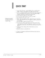
QUICK START
1. Connect the external power supply (included) to the rear panel connector
labeled “DC input.” Then plug the power supply into an AC outlet.
2. Connect a microphone cable between the Clear-Com line input connector on
the rear panel and the output connector of a Clear-Com PIC-4000 IFB
controller, or alternately, to a Clear-Com intercom system.
3. Set the “input level” switch to the “line” position.
4. Set the rear panel “audio compression” switch to “soft ALC.”
5. Turn on the front panel “power” switch.
6. With an audio input applied to the unit, adjust the front panel “input level
adjust” control until the “audio level” bargraph meter indicates peaks in the 0
to +2 VU range.
7. Attach the earpiece or headset to the RCV-2 receiver.
8. Turn the receiver on by moving the slide switch to the F1 or F2 position.
A short flash of the red “Batt Low” LED indicates a good battery. A steady
LED indicates a weak battery. If the LED does not turn on at all, replace the
battery.
9. Verify operation by switching to F1 or F2 which selects one of two
frequencies.
10.Adjust the volume to a comfortable level.
See Chapter 3 for detailed setup information and for instructions on how to
optimize performance.
• Follow these instructions
to quickly get the system
up and running.
1
Summary of Contents for RCV-2
Page 1: ...UPX 10 TRANSMITTER I N S T R U C T I O N M A N U A L WIRELESS IFB CUE SYSTEM RCV 2 RECEIVER...
Page 4: ...W i r e l e s s I F B C u e S y s t e m...
Page 6: ...W i r e l e s s I F B C u e S y s t e m...
Page 10: ...W i r e l e s s I F B C u e S y s t e m 2 4...
Page 23: ...I M F 1 0 2 I N T E R F A C E M O D U L E F R A M E 6 3 NOTES...
Page 24: ...I M F 1 0 2 I N T E R F A C E M O D U L E F R A M E 6 4 NOTES...