Clear-Com RCV-2 Instruction Manual Download Page 15

W i r e l e s s   I F B / C u e   S y s t e m

3 - 5

The battery door will unlatch after being moved only a short distance. Once the 
lower end of the door is free, swing it upwards on the hinge to expose the battery 
compartment. The door is attached to the case and should not be removed.

Insert the battery into the battery compartment with the “plus” (+) terminal 
towards the bottom of the unit. The battery should slide in freely. Fold the 
battery door back down and press it against the side of the unit. If the door does 
not close easily it is likely that the battery is inserted backwards. Slide the door 
upward towards the top of the RCV-2 while holding the door closed. There 
should only be slight resistance when sliding the door.

2. CHECK THE POWER

Turn on the power to the RCV-2 by sliding the switch on the top of the unit 
towards the center of the unit to the “1” mark. If the battery is correctly inserted 
and in good condition, the small LED indicator in the center of the receiver top 
panel will flash briefly and then go out. If the LED does not flash, the battery is 
not good or is not properly inserted. If the LED indicator stays on, the battery is 
low and must be replaced.

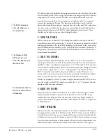
3. SELECT THE CHANNEL

Select the desired channel (frequency) on the RCV-2. One or two frequencies 
may be provided with your unit. If the identification label on the lower back of 
the RCV-2 shows two different frequencies (i.e. 171.045 and 171.905) you have 
a two-channel unit (RCV-2D). Select the desired frequency by sliding the switch 
on the receiver top panel to “1” or “2” as appropriate. The frequency of the 
RCV-2 receiver must match the frequency of the transmitter. If you are not 
certain of the transmitter frequency, check the transmitter identification label to 
make certain that you have a precise match with the RCV-2 channel.

If only one frequency is listed, you have a single channel unit (RCV-2S). In this 
case, the switch on the RCV-2 may be in either the “1” or “2” position as both 
positions will be the same channel.

4. ADJUST THE VOLUME

Adjust the volume control on the RCV-2 to minimum by turning the volume 
control towards the headset jack and away from the switch until the stop is 
reached. Do not attempt to force the control past the stop. Plug a headset or 
earpiece into the jack on top of the RCV-2 and adjust the headset or earpiece for 
a comfortable fit.

5. VERIFY OPERATION

Make certain that the companion transmitter is turned on and has audio input at 
the approximate normal level. Slowly turn the RCV-2 volume control clockwise 
towards the switch on the receiver top panel. If audio is not heard within the first 
few degrees of rotation of the volume control, it is likely that something is wrong.

Do not


continue to advance volume control. Check to see if the transmitter is on 

and has audio input. Also check to make certain that the RCV-2 has a good 

• The  RCV-2  receiver  is 

built with either one or 

two frequencies. 

• The frequency of the 

RCV-2 receiver must 

match the frequency of 

the transmitter. 

• The identification label on 

the transmitter will show 

its frequency. 

Summary of Contents for RCV-2

Page 1: ...UPX 10 TRANSMITTER I N S T R U C T I O N M A N U A L WIRELESS IFB CUE SYSTEM RCV 2 RECEIVER...

Page 2: ...rved Part Number 810179 Rev D Clear Com Intercom Systems 4065 Hollis Street Emeryville CA 94608 3505 U S A Clear Com is a registered trademark of Clear Com Intercom Systems The Clear Com Logo is a reg...

Page 3: ...taching the Antenna 3 1 Connecting the System 3 2 Adjusting the Settings 3 3 Initial Settings 3 3 Audio Level Setting 3 4 Audio Frequency Response and Dynamic Range Adjustments 3 4 Installing the Clea...

Page 4: ...W i r e l e s s I F B C u e S y s t e m...

Page 5: ...ith an audio input applied to the unit adjust the front panel input level adjust control until the audio level bargraph meter indicates peaks in the 0 to 2 VU range 7 Attach the earpiece or headset to...

Page 6: ...W i r e l e s s I F B C u e S y s t e m...

Page 7: ...adjusting the low and high frequencies are located on the rear panel In addition the audio dynamic range can be limited by either a 2 1 logarithmic compressor or by a wide range Automatic Level Contro...

Page 8: ...Part 90 or Part 74 It is compatible with the Clear Com UPX 10 and WBS 6 600 transmitters Note Any change or modification made to this product without the express written authorization and approval fr...

Page 9: ...s the RCV 2 to be recharged without removing the battery and without disconnecting or dissassembling the headset Antenna The RCV 2 receiver uses the headset or earpiece cable as the antenna For best p...

Page 10: ...W i r e l e s s I F B C u e S y s t e m 2 4...

Page 11: ...chable rack mounted ears must first be installed on the UPX 10 as follows 1 Loosen but do not remove the four screws on the two sides of the unit that hold the top cover onto the chassis 2 Slide the t...

Page 12: ...UPX 10 through the XLR connector located on the rear panel The base station comes with the internal jumpers programmed for use with a Clear Com intercom system The pin assignments are consistent with...

Page 13: ...operation ADJUSTING THE SETTINGS There are no user serviceable adjustments located inside the UPX 10 In addition normal setup and operation does not require internal access Refer all service and inter...

Page 14: ...mic range setting is selected it will be necessary to readjust the variable audio level control to achieve the O VU reading on the front panel bargraph If the VU meter consistently reads higher than O...

Page 15: ...a two channel unit RCV 2D Select the desired frequency by sliding the switch on the receiver top panel to 1 or 2 as appropriate The frequency of the RCV 2 receiver must match the frequency of the tran...

Page 16: ...permanent effects including hearing loss The use of low impedance 8 to 20 Ohms and high efficiency headsets and earpieces with the RCV 2 should be limited to those with existing hearing impairments A...

Page 17: ...eplacing the battery with a fresh unit in the event of any sort of problem with the system because a low battery may affect system operation in subtle ways When you turn off the power to the UPX 10 tr...

Page 18: ...ese include furniture lighting fixtures scaffolding electrical cables metal structural members aluminum window frames and equipment cabinets Whip and dipole antennas require at least 5 inches 12 7 cm...

Page 19: ...Rear panel mounted slide switch Audio Input Level Line 10 to 20 dBu Mic 40 to 10 dBu Audio Input Adjust Range 30 dB Audio Frequency Compensation Low 10 dB High 10 dB Front Panel Controls and Indicato...

Page 20: ...ortion 1 typical 1 kHz Signal to Noise Ratio 78 dB minimum Audio Output 100 milliwatts minimum into 8 Ohms Power 9 volt battery accepts 9 2 to 6 3 VDC Current Drain 40 milliamps max with 10 milliwatt...

Page 21: ...e implied warranty of merchantability are limited to the duration of this express limited warranty Neither Clear Com nor the dealer who sells Clear Com products is liable for incidental or consequenti...

Page 22: ...ized service facilities If requested an estimate of repair costs will be issued prior to service Once repair is approved and repair of equipment is completed the equipment will be shipped freight coll...

Page 23: ...I M F 1 0 2 I N T E R F A C E M O D U L E F R A M E 6 3 NOTES...

Page 24: ...I M F 1 0 2 I N T E R F A C E M O D U L E F R A M E 6 4 NOTES...

Reviews: