background image

HeatingSect_SM45_b.fm

A-10

04/30/2019

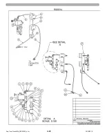
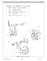
Fig. 01C - Main Heating Section–SM40

Summary of Contents for Steam Master CSMG-15

Page 1: ...STEAM MASTER SERIES USER MANUAL Cover CSMG 15 30 40 R027880B 20190603 ...

Page 2: ... your unit s specific model and serial number in the space below The model and serial number are located on the right hand side of the electronic controls cabinet MODEL _______________________ SERIAL NUMBER _____________________ ...

Page 3: ...y disassembly of the steam generator Disconnect main power and properly lockout disconnect switch S10 before working on any electrical component inside the electrical control panel High voltage and moving parts hazards exists around the blower and feedwater pump motors and pulley systems Equipment may start automatically at any time HEARING PROTECTION Elevated ambient noise levels exist in the fac...

Page 4: ...RIOR TO THE STEAM GENERATOR INSTALLATION DAMAGE TO ELECTRONIC EQUIPMENT NOT COVERED BY THE CLAYTON WARRANTY MAY RESULT FROM INSTALLATION ACTIVITIES IF THIS ACTION IS NOT TAKEN Steam generator electronics cabinet devices are rated to function properly at typical boiler room temperatures not exceeding 122 F 50 C For boiler room installations where temperatures are expected to exceed 122 F 50 C an el...

Page 5: ...s for assembly and operations of controls and safety devices CANADA BOILERS A Current Edition of Canadian Standards Association CSA B139 Installation Code for Oil Burning Equip ment for recommended installation practices B The equipment shall be installed in accordance with the current installation code for gas burning appliances and equipment CGA B149 and applicable provincial regulations for the...

Page 6: ...nt MUST be used to move your steam generator IT IS YOUR RESPONSIBILITY TO INSPECT YOUR UNIT BEFORE UNPACKING AND AFTER UNPACKING FOR DAMAGES THAT MAY HAVE OCCURRED DURING SHIPPING The steam generator is anchored to the pallet by two bolts One of the two anchor bolts is located at the front left corner of the unit inside the front left door The second of the two bolts is located at the right rear c...

Page 7: ...ages describe the controls and other features of the Clayton Steam Master These pages are only a general overview The controls and features may differ depending on the unit s size and specifications See page viii for description of unit features ...

Page 8: ...vi The controls and features may differ depending on the unit s size and specifications ...

Page 9: ...vii The controls and features may differ depending on the unit s size and specifications ...

Page 10: ...ump and Motor Assembly 14 Heating Coil 20 Water Inlet Pump 24 Feedwater Pressure Gauge 25 Maintenance Drain Valve 26 Coil Feedwater Valve 29 Test Valve 30 Safety Relief Valve 32 Separator Drain Valve 38 Steam Pressure Gauge 41 Steam Trap Pressure Gauge 47 Steam Outlet Valve 48 Steam Trap B24 Pressure Transducer OPX1 B29 Temperature Transmitter F21 Temperature Switch LPS F31 Thermocouple F95 Temper...

Page 11: ... ing The NBBI is a nonprofit organization Its chief boiler and pressure vessel inspectors are responsible for administering the boiler and pressure vessel safety laws of their jurisdiction Clayton Steam Generators are designed with electrical and combustion safeguards which comply with UL Underwriters Laboratories and other such agency require ments as specified in a customer s order NBBI certific...

Page 12: ...herwise without written permission from Clayton Industries The descriptions and specifications shown were in effect at the time this publication was approved for printing Clayton Industries whose policy is one of continuous improvement reserves the right to discontinue models at any time or change specifications or design without notice and without incurring any obligation FACTORY DIRECT SALES AND...

Page 13: ...mp 0 75 Blower 0 67 Pump 0 75 Blower 0 83 Pump 1 5 Blower 0 83 Pump 1 5 Electric FLA based on 230 vac See Note 3 vac 10 10 11 11 15 15 Gas Supply Pressure Required psig 2 2 2 2 2 2 Water Supply Required gph 133 133 265 265 353 353 Heating Surface ft2 78 6 110 9 141 0 199 1 152 8 228 2 Customer Connections Feedwater Inlet in 1 5 1 5 1 5 1 5 1 5 1 5 Steam Trap Discharge in 1 0 1 0 0 75 0 75 1 0 1 0 ...

Page 14: ...Specifications_CSM_a fm xii 11 22 2018 This page intentionally left blank ...

Page 15: ...Protectors GMP 2 4 2 3 2 Gas Pressure Switch High GPSH 2 4 2 3 3 Gas Pressure Switch Low GPSL 2 4 2 3 4 Limit Pressure Switch LPS 2 5 2 3 5 Main Gas Valve MGV 2 5 2 3 6 Power Supply 2 5 2 3 7 Stepdown Transformer 115 VAC 2 5 2 3 8 Variable Speed Drive VSD 2 5 2 4 PLC Programmable Logic Controller 2 5 Section 3 Safety Precautions 3 1 3 1 1 Hot Components 3 1 3 1 2 Poorly vented Boiler Rooms 3 1 3 1...

Page 16: ...s 3 3 3 3 3 Freezing Conditions 3 3 3 3 4 Fluid Under Pressure 3 4 3 3 5 Water Hammer 3 4 3 3 6 Vacuum 3 4 3 4 Fuel and Air Piping 3 4 3 4 1 Poorly vented Boiler Room 3 4 3 4 2 Explosion Risk 3 4 3 4 3 Falling Risk 3 4 Section 4 Operating Instructions 4 1 4 2 Main Menu Screen 4 1 4 3 Start up Auto Mode 4 1 4 4 Start Mode 4 2 4 4 1 Easy Start 4 3 4 4 2 Operator Start 4 3 4 5 Manual Mode Operation 4...

Page 17: ...le Sensor 6 3 6 5 4 Check Main Temperature Limit Controllers MTLC 6 4 6 5 5 Clean Strainers 6 5 6 5 6 Drain and Flush Hot well Tank 6 5 6 5 7 Inspect Intake Surge Chamber and Snubber 6 5 6 6 Semi annual Service 6 6 6 7 Annual Service 6 6 6 7 1 Replace Check valves 6 7 6 7 2 Replace Feedwater Pump Diaphragms and Seals 6 7 6 7 3 Test Steam Safety Valve 6 7 6 7 4 Service Compact Burner Unit 6 7 6 8 H...

Page 18: ... 40 A 16 Fig 02C Steam Trap and Control Valve Hookup A 18 Fig 02D Safety Relief Valve Hookup A 19 Fig 02E Pressure Indicating System A 20 Fig 04A Feedwater Pump Hookup C1 A 22 Fig 04B Feedwater Pump Hookup C2 A 23 Fig 05A Pump Assy C1 A 24 Fig 05B Pump Assy C2 A 26 Fig 06 Check Valve A 28 Fig 07 Relief Valve A 28 Fig 09 Fuel Gas System A 29 Fig 13 Electrical Control Box A 30 Fig 18 Separator High ...

Page 19: ... operation and mainte nance requirements of the Clayton Steam Genera tor The information contained in this manual applies to gas fired machines Section II of this manual acquaints you with the machine This sec tion provides an overview and descriptions of a machine s systems such as the water supply and fuel system The machine overview includes a dis cussion on the theory of operation of a Clayton...

Page 20: ...hould be installed before placing the steam generator into service Daily treatment and care of the feedwater supply is the sole responsibility of the user Continuous feedwater treatment is required at all times even during the periods of wet lay up shutdowns Water testing must be conducted daily even during the periods of wet lay up shutdowns A separate feedwater treatment manual part num ber R015...

Page 21: ...plus liquid is returned to the hot well tank through the steam trap mounted on the steam separator 2 2 2 Feedwater Pump The Clayton positive displacement dia phragm type feedwater pump ensures a wet tube heating coil by delivering the required volume of water to the heating coil under all load conditions A reciprocating pump diaphragm displaces feedwa ter through the discharge side of the check va...

Page 22: ...e manually reset before normal operation can be resumed This is done through 010 A STEAM COIL TEMP OVER LIMIT safety shutdown condition will be indicated on the OIU and an audible alarm will sound Fig 2 1 Water and Steam System typical OPTIONAL ECONOMIZER A B C D E A Steam Discharge Valve B Coil Feed Valve C Feedwater Pump D Feedwater Valve E Separator Drain Valve F Coil Drain Valve F 1 See the Ta...

Page 23: ...perature rise above the saturation temperature for the corresponding operating pres sure indicates a water shortage condition Table 2 1 Pressure Temperature GAUGE PRESSURE PSIG TEMP F GAUGE PRESSURE kPa TEMP C GAUGE PRESSURE PSIG TEMP F GAUGE PRESSURE kPa TEMP C GAUGE PRESSURE PSIG TEMP F GAUGE PRESSURE kPa TEMP C 5 228 34 4 109 220 396 1 516 8 202 420 453 2 895 7 236 10 240 68 9 115 230 399 1 585...

Page 24: ...a decrease in fuel pressure will increase the trapping time A decrease in the pump rate will decrease trapping time Trap open time should not fall below twelve minutes per hour at high fire and four minutes per hour at low fire accumulated under any conditions 2 3 Control Devices 2 3 1 Group Motor Protectors GMP The group motor protectors function as a 3 phase manual motor starter protector for co...

Page 25: ...variable frequency input to the feedwater pump motor s dictating the rpm of the feedwater pump s It is controlled by a 4 20 mA reference voltage signal from the PLC Detailed information on operation programming and troubleshooting is provided in VSD manufac turer s operators manual provided at time of initial startup 2 4 PLC Programmable Logic Controller The PLC is responsible for the monitoring a...

Page 26: ...Sect02_CSMG_b fm 2 6 04 19 2019 Steam Master Instruction Manual This page intentionally left blank ...

Page 27: ...oving Parts Injury to body or clothing All rotating parts are screened off If screens are removed for maintenance or repair make sure to cut the electrical power on this particular part Use a lock or remove the key from the switch If you need to work on parts without protective screens make sure not to wear loose clothing such as ties open coats etc Only authorized personnel should be present near...

Page 28: ...he steam escapes and the fixing of the piping gets damaged 3 1 13 Pre stressed Springs Injuries by mechanical impact Loosening parts with pre stressed springs can cause injuries by a sudden position change of the parts Check out how these parts are interlinked first Use accessories such as pins to disassemble parts with pre stressed springs Parts not strong enough to support heavy weights some par...

Page 29: ...ntenance and repair If required seek additional personnel for assistance 3 2 5 Compressed Springs The feedwater pump diaphragm springs are under compression in the pumphead housing Unseat pumphead housing carefully 3 2 6 Electrical Parts Lock out the main circuit power before working on feedwater pump to prevent unexpected motor start 3 2 7 Human Error Only personnel who are properly trained to wo...

Page 30: ...us access point openings 3 4 FUEL AND AIR PIPING 3 4 1 Poorly vented Boiler Room The heating coil is surrounded by an air cover under a predefined over pressure As a result combustion gases can only exit the unit through an exhaust duct However if this air cover fails combustion gases will escape into the boiler room This problem could occur when the air supply to the ventilator is blocked and hen...

Page 31: ...ll appear on the main menu screen as shown in Fig 4 1 The icons will be either active or inactive depending on the operator access level The advanced level screens require user login Once logged in the icons for the advanced level screens will become active 4 3 START UP AUTO MODE The default start is auto mode The unit may be transferred into manual mode by the AUTO MANUAL button on the main menu ...

Page 32: ...ied to be in the correct position acknowledge that valve on the screen The unit will start the light off sequence The FIRING IN AUTO screen will display Fig 4 5 The burner unit will proceed through its preprogrammed light off sequence and light off when the sequence is completed The steam pressure steam temperature and firing rate information is displayed on this screen These values are fixed 4 4 ...

Page 33: ...DE OPERATION The manual operating mode is reserved for more advanced knowledgeable users who are thoroughly familiar with the Clayton Steam Master steam generator Clayton recommends transferring over to manual mode operation ONLY AFTER the unit has completed its start process and is running normally Manual mode operation requires the operator to be present and actively monitoring the unit througho...

Page 34: ... The unit may be transferred back to manual fill mode at any time during the manual firing mode by returning to the main menu and selecting the RUN TO FILL icon 4 6 RESTART AFTER MOMENTARY SHUT DOWN A unit that had its operation disrupted by the operator or by an alarm condition may still have a filled or partially filled coil In either case the operator has the option to skip the coil fill proces...

Page 35: ...are no leaks anywhere in the plumbing during wet lay up 4 8 DRY SHUT DOWN The unit will develop rust or other forms of oxidation inside the coil tubing if dry shut down is executed improperly A dry shut down should be performed by Clayton service personnel or other personnel who are thoroughly trained in Clayton steam generators A dry shut down maintains a dry coil when a unit will be shut down fo...

Page 36: ...g 4 1 on page 4 1 Once logged in the icons for the advanced user level screens will become active 4 9 1 Modify Set Point and Tune PID Screens Fig 4 12 Slowly close steam header valve to maintain pressure during dry shutdown Fig 4 13 Modulation setpoints screen Enter modulation setpoint cut out setpoint and cut in setpoint from this screen Fig 4 14 PID Parameters screen The PID trend button will di...

Page 37: ... Screen 2 intermittent fill layup interfill and fill rate delay release temperature delay release pressure delay rate ramp release temperature ramp release pressure ramp release steam temperature Delta T ramp release time and stack temperature alarm setpoint can be entered on this screen Fig 4 19 Calibration Screen 3 post fill temperature post run temperature water level relay delay time water lev...

Page 38: ...e corrected before pressing the RESET icon 4 10 2 Alarm History This screen can be accessed by pressing the ALARM HISTORY icon on the main menu screen See Fig 4 1 on page 4 1 4 11 MAINTENANCE DRAIN The maintenance drain screen is typically used for maintenance procedures such as TDS control Fig 4 20 Alarm screen Fig 4 21 Alarm history screen Fig 4 22 Maintenance Drain screen ...

Page 39: ... to proper pressure See Sect 7 3 or replace if faulty Feedwater pump not primed Prime feedwater pump Strainer partially plugged Hot well tank drain open Float valve strainer plugged Correct accordingly Thermostat Low water condition Correct cause of low water or water failure condition Possible causes 1 Empty hot well tank 2 Clogged inlet strainer 3 Worn check valve seats and discs 4 Malfunctionin...

Page 40: ...ation Feedwater pump intake surge chamber malfunctioning Check rubber insert deflection Sect 6 5 7 and replace intake surge cham ber if required Feedwater pump discharge snubber malfunctioning Check rubber insert deflection Sect 6 5 7 and replace discharge snubber if required Worn bearings in crankcase Replace bearings if necessary Restricted heating coil causing exces sive back pressure Check fee...

Page 41: ...ary Trap gauge sensing line obstructed or trap gauge defective Clean sensing line Replace gauge if defective Steam trap pressure gauge registers fixed pressure reading Steam trap open Ensure feedwater pump is discharging at normal capacity Check for possible malfunctioning of steam trap or loss of trap prime Check modulating system controls Check burner operation for possible reduced heat input un...

Page 42: ...r failed LPS Replace LPS or correct cause of overpressure Check for low voltage Correct cause Motor noisy or running hot Motor running single phase Check for blown fuse in feeder lines Insufficient lubrication or bearing fail ure Lubricate bearings Check for worn bearings Excessive system pressure variation Modulating Pressure Setting Differen tial out of adjustment Adjust based on existing steam ...

Page 43: ...IONS AND MAINTENANCE MANUAL FOR TROU BLESHOOTING PROCEDURES Burner purge cycle fails to occur Modulating motor safety shut off valve ATS or other upstream con tacts open Modulating motor must be in low fire position Be sure gas valve SSGV or MGV proof of closure valve is not hung open ESC locked out Reset Circuit complete when burner flame safeguard display reads standby Check for cause of burner ...

Page 44: ...Sect05_CSMG_a fm 5 6 11 26 2018 Steam Master Instruction Manual NOTES ...

Page 45: ...ervice 6 3 1 Record Operating Steam Pressure Record the operating pressure in the Periodic Maintenance Log R027906 6 3 2 Trap Timing See paragraph 2 1 6 in Section 2 for details Record the trap pressure in the Periodic Main tenance Log 6 3 3 Test and Record Feedwater Record tested feedwater characteristics indi cated in Periodic Maintenance Log Refer to Clayton Feedwater Treatment Man ual R015216 ...

Page 46: ...er tension See Fig 6 2 Fingers will be crushed by spinning pump belt Prevent losing fingers by cutting power to the feedwater pump motor a Remove the five Allen screws that attaches the top cover to the feedwater pump compartment b Remove the top cover c Check belt tension Belt play checked midway between the two pulleys should be no more than the thickness of the belt d Adjust belt tension as req...

Page 47: ...ied in this manual to remove solids that are precipitated in the form of sludge The blowdown operation is not a cure all but it will remove some scale and thereby delay coil restriction NOTE The Feedwater Treatment Manual contains detailed information with regards to the importance of feedwater treatment and the recommended procedures and equipment necessary to prevent scale and corrosion within t...

Page 48: ...nt thermocou ple sensor d Record the steam temperature Remove the meter leads from the secondary ele ment when done e Record the feedwater temperature read ing on the thermometer on or near the feedwater pump Alternatively a feedwater temperature reading from the thermometer on the hot well tank may be used 6 5 3 3 Evaluate recorded values a The results from steps 6 5 3 1b and 6 5 3 1d should fall...

Page 49: ... Industries Feedwater Treatment Reference Manual P N R015216 for additional feedwater quality requirements Secure the machine before performing this maintenance procedure a Open the drain valve at the base of the hot well tank and allow the water to com pletely drain b Close the drain valve c Fill the tank with clean potable water d Open the drain valve to drain the tank Verify the water draining ...

Page 50: ...snubber requires replacement 6 6 Semi annual Service Test feedwater pump relief valve Fig 6 5 operation Slowly close the coil feed valve until the feedwater discharge pressure exceeds the relief valve s set pressure typically 275 psi 1 896 kPa Verify relief valve is discharging properly and ver ify the drain lines are clear of blockage for proper draining See Section 7 2 adjustment and mainte nanc...

Page 51: ...vice or replace steam safety valve if test fails 6 7 4 Service Compact Burner Unit 1 Servicing must be performed by a well qualified and experienced service technician only Standard maintenance of the Weishaupt compact burner unit to be performed once a year by qualified and experienced personnel Servicing to be performed according to the guidelines outlined in the Weishaupt Installation and Opera...

Page 52: ...ere is no outlet at the bottom of the container fasten a fine mesh screen over the end of the hose and place that end of the hose inside the container Secure the hose to the container to prevent it from slipping out NOTE A shutoff valve may be installed at the outlet of the container This will aid in preventing any acid spillage from the container when the suction hose is disconnected from the con...

Page 53: ...e feedwater pump housings are primed Wear protective clothing Mishandling of the acid may cause serious personal injury c Mix 3 ounces 89 milliliters of KleenKoil Inhibitor to one gallon 3 8 liters of hydrochloric acid HCl or one can of KleenKoil Inhibitor to 5 gallons 19 liters of HCl d SLOWLY add this acid solution to the con tainer Monitor the feedwater in the container for foaming Continue add...

Page 54: ...n has circulated for the two additional hours 6 8 3 After Descaling Is Complete Acid solution will burn face arms and other body parts Carefully disconnect hoses to avoid spilling acid solution If a shutoff valve was installed at the container close the valve before disconnecting suction hose NOTE Discharging the acid solution into a local sewage system may be in violation of municipal codes and r...

Page 55: ...fm Section VI Periodic Maintenance NOTE Start the machine and blowdown the machine thoroughly four to five times See Section 4 8 of Section IV before resuming normal operation This will dislodge and remove much of the loosened scale ...

Page 56: ...Sect06_CSMG_b fm 6 12 04 22 2019 Steam Master Instruction Manual This page intentionally left blank ...

Page 57: ... tion Feedwater pump belt adjustment and replacement is performed as follows a Remove the five Allen bolts securing the top cover and remove cover See View A in Fig 7 1 b Remove the two Allen bolts securing the side cover and remove cover See View B in Fig 7 1 c Loosen the four motor base adjusting nuts to lower the motor base See Fig 7 2 d Loosen each of the four adjusting nuts to relieve the bel...

Page 58: ...h free length of intake springs 2 should be 1 2 inch Replace broken or distorted springs c Damaged seats 1 may be removed with a screw extractor E Z Out Turn extractor while lifting firmly until seat is removed Drive replacement seats in place with a special seat driving tool part no UH 18389 to avoid damage to the seat face 7 2 2 Replacing Check Valve Seats To replace valve seats use a special se...

Page 59: ...ime for pumphead fluid to cool before draining and disassembling pumphead c Unscrew the eight attaching pumphead hex nuts 15 and remove pumphead check valve assembly d Unscrew the cap screw 14 and remove the top diaphragm washer 3 and the old diaphragm 4 Note the orientation of the top diaphragm washer as it is installed e Install the new diaphragm and the top dia phragm washer Make sure the top d...

Page 60: ...ankcase 10 Washer 11 Screw 12 Retaining Plate 13 Washer 14 Screw 1 15 Nut 2 16 Stud 17 Pump Head 18 Pipe Plug 19 Bearing Spacer End 20 Washer 21 Connecting Link Bearing 22 Crankshaft Bearing 23 Crankshaft 24 Check valve Seat 25 Intake Spring 26 Check valve Cap 27 Gasket 28 Discharge Spring 29 Check valve Disc 30 Plug 31 Check valve Housing ported 1 Torque 30 ft lb 2 Torque 35 ft lb Fig 7 5 C2 feed...

Page 61: ...laring which can interfere with the pulley installation Instead place a piece of 2x4 lumber against the shaft end and strike the piece of lumber e Remove the crankshaft bearing 22 that is farthest from the pulley with a bearing pulling tool f Remove the connecting link bearing crankshaft assembly from the crankcase g Pull the remaining crankshaft bearing 22 connecting link 8 and bearing 21 from th...

Page 62: ...iver 1 14 thread a Thoroughly clean both the studs and the threaded crankcase holes of all dirt oil and other debris Use clean solvent b Spray primer Locquic T Primer only on the short threaded end of the cleaned stud Do not over prime A very thin film is best Inhaling primer fumes will cause loss of consciousness Use primer in a well ventilated area c Apply adhesive Loctite 242 at lead threads in...

Page 63: ...scharge begins check the pressure on the feed pressure gauge b To raise the pressure adjustment turn the adjusting screw clockwise Similarly to lower the pressure adjustment turn the adjusting screw counterclockwise Secure the adjusting screw with the lock nut after adjustment process It is best to make these pressure adjustments while the feedwater pump is off A feedwater pump that is running pla...

Page 64: ...s about halfway between the original OPS setpoint and the opening pressure of the steam safety relief valve s Operate the machine and slowly throttle the steam discharge valve to increase the steam pressure to desired LPS setpoint Set the limit pressure switch dial down to open shutting machine off Reset the OPS to its original setting See paragraph 7 5 7 7 Gas Pressure Switches Damage to burner u...

Page 65: ...n dial until the desired pressure set point is aligned with the white line on the yellow dial face c Verify the switch operates as intended d Replace cover Fig 7 10 GPSL GPSH adjustment dial and manual reset button The GPSL installed at the main gas inlet requires a manual reset The GPSH located inside the packaged burner unit housing requires a manual reset ...

Page 66: ...Sect07_CSMG_b fm 7 10 04 26 2019 Steam Master Instruction Manual This page intentionally left blank ...

Page 67: ...d Separator Hookup SM 15 A 14 Fig 02B Steam Discharge and Separator Hookup SM 30 40 A 16 Fig 02C Steam Trap and Control Valve Hookup A 18 Fig 02D Safety Relief Valve Hookup A 19 Fig 02E Pressure Indicating System A 20 Fig 04A Feedwater Pump Hookup C1 A 22 Fig 04B Feedwater Pump Hookup C2 A 23 Fig 05A Pump Assy C1 A 24 Fig 05B Pump Assy C2 A 26 Fig 06 Check Valve A 28 Fig 07 Relief Valve A 28 Fig 0...

Page 68: ...HeatingSect_SM15_a fm A 2 04 30 2019 Fig 01A Main Heating Section SM15 ...

Page 69: ...04 30 2019 A 3 HeatingSect_SM15_a fm FIG 01A Main Heating Section SM15 ...

Page 70: ...HeatingSect_SM15_a fm A 4 04 30 2019 Fig 01B Economizer Stack Outlet Kit SM15 ...

Page 71: ...04 30 2019 A 5 HeatingSect_SM15_a fm FIG 01B Economizer Stack Outlet Kit SM15 ...

Page 72: ...HeatingSect_SM30_b fm A 6 12 05 2018 Fig 01C Main Heating Section SM30 ...

Page 73: ...12 05 2018 A 7 HeatingSect_SM30_b fm FIG 01C Main Heating Section SM30 ...

Page 74: ...HeatingSect_SM30_b fm A 8 12 05 2018 Fig 01D Economizer Coil SM30 ...

Page 75: ...12 05 2018 A 9 HeatingSect_SM30_b fm FIG 01D Economizer Coil SM30 ...

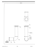
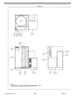
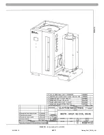
Page 76: ...HeatingSect_SM45_b fm A 10 04 30 2019 Fig 01C Main Heating Section SM40 ...

Page 77: ...04 30 2019 A 11 HeatingSect_SM45_b fm FIG 01C Main Heating Section SM40 ...

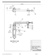
Page 78: ...HeatingSect_SM45_b fm A 12 04 30 2019 Fig 01D Economizer Coil SM40 Sht 1 of 2 ...

Page 79: ...04 30 2019 A 13 HeatingSect_SM45_b fm FIG 01D Economizer Coil SM40 ...

Page 80: ...Sep Trap PressMfld_SM153040_b fm A 14 04 30 2019 Fig 02A Steam Discharge and Separator Hookup SM 15 ...

Page 81: ...04 30 2019 A 15 Sep Trap PressMfld_SM153040_b fm FIG 02A Steam Discharge and Separator Hookup SM 15 ...

Page 82: ...Sep Trap PressMfld_SM153040_b fm A 16 04 30 2019 Fig 02B Steam Discharge and Separator Hookup SM 30 40 ...

Page 83: ...04 30 2019 A 17 Sep Trap PressMfld_SM153040_b fm FIG 02B Steam Discharge and Separator Hookup SM 30 40 ...

Page 84: ...ne 3 8 in 1 3 0019348 VALVE Globe 1 in 800 3 0019929 VALVE Globe 3 4 in 800 3 0020001 VALVE Globe 1 2 in 800 3 4 0019929 VALVE Globe 3 4 in 800 feedwater 1 0020001 VALVE Globe 1 2 in 800 feedwater 1 5 0019348 VALVE Globe 1 2 in 800 steam discharge 1 0020191 VALVE Globe 1 1 2 in 800 steam discharge 1 6 0018525 TRAP Steam 213 1 in 1 4 in 1 0033152 TRAP Steam 211 1 2 in 1 8 in 1 0033203 TRAP Steam 21...

Page 85: ...04 30 2019 A 19 Sep Trap PressMfld_SM153040_b fm Fig 02D Safety Relief Valve Hookup FIG 02D Safety Relief Valve Hookup ...

Page 86: ...Sep Trap PressMfld_SM153040_b fm A 20 04 30 2019 Fig 02E Pressure Indicating System ...

Page 87: ...04 30 2019 A 21 Sep Trap PressMfld_SM153040_b fm FIG 02E Pressure Indicating System ...

Page 88: ...2 in 275 psi See Fig 07 for details 1 2 UH23304 VALVE Check 1 1 4 in See Fig 06 for details 1 3 UH27215 CHAMBER ASSY Intake Surge 1 4 UH24615 SNUBBER ASSY Discharge 300 psi 1 5 UH40129 PUMP ASSY Water C1 See Fig 05A for details 1 6 0030484 VALVE Ball lockable 1 1 2 in 1000 psi 1 7 0031462 BELT V 3VX500 1 8 0040868 MOTOR 1 hp 1200 rpm TEFC 145T 1 1 2 4 3 7 8 5 6 ...

Page 89: ... Fig 07 for details 1 2 UH23304 VALVE Check 1 1 4 in See Fig 06 for details 1 3 UH27215 CHAMBER ASSY Intake Surge 1 4 UH24615 SNUBBER ASSY Discharge 300 psi 1 5 UH39671 PUMP ASSY Water C2 See Fig 05B for details 1 6 0030484 VALVE Ball lockable 1 1 2 in 1000 psi 1 7 0031462 BELT V 3VX500 1 8 0038193 MOTOR 3 4 hp 1200 rpm TEFC 1 0041360 MOTOR 2 hp 1800 rpm TEFC 1 1 2 3 4 5 7 8 6 ...

Page 90: ...PumpHkup C1 C2_parts_a fm A 24 03 05 2019 Fig 05A Pump Assy C1 ...

Page 91: ...03 05 2019 A 25 PumpHkup C1 C2_parts_a fm FIG 05A Pump Assy C1 ...

Page 92: ...03 05 2019 A 26 PumpHkup C1 C2_parts_a fm Fig 05B Pump Assy C2 ...

Page 93: ...PumpHkup C1 C2_parts_a fm A 27 03 05 2019 FIG 05B Pump Assy C2 ...

Page 94: ...H18285 SPRING 1 4 UH25196 DISC 1 5 UH25189 SEAT Rulon Used on UH21728 and UH23304 1 UH62860 SEAT Stainless Steel Used on UH30530 1 6 UH12722 HOUSING Used on UH21728 and UH30530 1 UH15479 HOUSING Used on UH23304 1 Item Part No Description Qty UH30824 VALVE ASSY Relief 1 2 in 275 psi Ref 1 0027740 SCREW 3 8 16 x 1 1 2 in 1 2 0012100 NUT 3 8 16 1 3 UH13659 BODY 1 4 UH13660 SEAT Stainless Steel 1 5 UH...

Page 95: ...LVE Ball bronze 3 4 in DN20 2 8 SWITCH Pressure 1 0 in 20 0 in w c 1 PN30W MOP5 17 80 GML A4 4 4 Dungs 266945 VALVE Ball bronze 1 in DN25 CW510L 2 SWITCH Pressure 12 0 in 60 0 in w c 1 3 ACTUATOR Gas Valve P O C SKP25 011U1 1 GML A4 4 6 Dungs 266947 Clayton equivalent part no 0039296 9 VALVE Solenoid 3 4 in 120v 60Hz Asco 1 4 BODY Gas Valve 3 4 in VGG10 204U 1 8214G030 Clayton equivalent part no 0...

Page 96: ...ControlBox_CSM_a fm A 30 11 20 2018 Fig 13 Electrical Control Box FIG 13 Electrical Control Box 1 5 13 13 22 4 7 7 20 21 23 25 24 18 11 14 15 16 17 2x 10x 3x 50x 29 31 12 27 28 30 6 10 9 8 4x 26 ...

Page 97: ...h Level Alarm Kit FIG 18 Separator High Level Alarm Kit Item Part No Description Qty 1 0038294 SENSOR Conductance water level 1 2 0038263 PROBE Sensor conductance 1 3 0039202 CONTROL Liquid Level octal 1 3 1 2 INSIDE LEFT DOOR OIU E STOP PUSHBUTTON ...

Page 98: ...Blank_Left fm A 32 08 16 2017 This page intentionally left blank ...

Page 99: ...Indication and Control B 3 Fig 04 Water Temperature and Blowdown Tank Hookup B 3 Fig 05 Sparger Tubes Water Heating B 4 Fig 06 TDS Control System Equipment Option B 4 Fig 07 Circulation Pump Hookup TDS System B 5 Fig 08 Booster Pump Hookup B 5 Fig 09 Sample Cooler Water Sampling B 5 Fig 10 Optional Sparger Tube Water Heating B 5 ...

Page 100: ...ain EFC 30 1 F 0040724 Water Softener 60 000 grain EFC 60 1 F 0040841 Water Softener 90 000 grain EFC 90 1 F 2 0040829 Valve Solenoid 2 way 1 2 in Make up Water Valve 3 0029872 Valve Ball 1 in 1000 psi 0033793 Valve Ball 3 4 in 1000 psi 4 0037877 Valve Ball 1 4 in 1000 psi 5 0029872 Valve Ball 1 in 1000 psi 6 0016389 Gauge Pressure 2 in 7 0003440 Valve Ball 1 4 in 8 0033793 Valve Ball 3 4 in 1000 ...

Page 101: ...ss Bottom Glass Level 0037744 Receptacle 3 prong GFCI 0039202 Control Liquid Level 0038581 Box Receptacle Rain tight 0038581 Box Receptacle Rain tight Fig 4 Water Temperature and Blowdown Tank Hookup Table 3 1 0019567 Thermometer 3 1 2 in 300 F 2 0038293 Switch Temperature 100 300 F 3 0033793 Valve Ball 3 4 in 1000 psi Hotwell Drain Valve 4 0017096 Valve Regulator Temperature 3 4 in 5 0033793 Valv...

Page 102: ...d 1 2 in 6 0038194 Valve Ball 1 2 in Gravity Fill Hookup 7 0019929 Valve Globe 3 4 in Equipment Option Fig 6 TDS Control System Equipment Option 2 1 5 6 7 5 3 4 Table 5 1 0051007 Controller TDS WBLW100HN A 2 0038172 Pump Chemical 14 gpd EZB11D1 PEM 0038536 Pump Chemical 14 gpd EWB11Y1 PCM 0038568 Pump Chemical 50 gpd EWN C21PEURM 3 0038194 Valve Ball 1 2 in 4 0030227 Coupling 1 2 in 5 0025603 Valv...

Page 103: ...LER 1 4 Fig 8 Booster Pump Hookup 6 7 8 9 9 3 4 1 2 3 5 Table 7 1 0037864 Gauge Pressure 2 1 2 in 0 60 psi 2 0030491 Tube Syphon Loop 1 4 in 3 0003440 Valve Ball 1 4 in FPT MPT 4 0030484 Valve Ball 1 1 2 in 1000 psi 0030486 Valve Ball 2 1 2 in 1000 psi 5 0033095 Pump Centrifugal 1 2 hp 230 460 v 0037910 Pump Centrifugal 1 2 hp 575 v 0044875 Pump Centrifugal 3 4 hp 575 v 6 0030485 Valve Ball 2 in 1...

Page 104: ...25 75 bhp Feedwater Skid Option FeedwtrSkid_VHtwl_25 75bhp_a fm B 6 11 26 2018 This page intentionally left blank ...

Page 105: ...G PRESSURE PSI COIL FEED PRESSURE PSI HARDNESS DATE STEAM TRAP PRESSURE PSI STACK TEMPERATURE o F TDS 3 000 6 000 PPM FEEDWATER TREATMENT SULFITE 50 100 PPM pH 10 5 12 5 PERIODIC MAINTENANCE LOG WALK AROUND INSPECTION MODEL SERIAL NUMBER TIME CUMULATIVE OPERATING HOURS MONTHLY WHILE UNIT IS SHUT DOWN WHILE UNIT IS OPERATING TEMPERATURE CONTROLLERS WEEKLY CHECK BELT TENSION PARTIALLY DRAIN HOTWELL ...

Page 106: ...R027906A 2018 10 22 ...

Page 107: ...NOTES ...

Page 108: ...Steam Generator Instruction Manual This page intentionally left blank ...

Page 109: ......

Page 110: ...17477 Hurley Street City of Industry California 91744 5106 USA Email sales claytonindustries com Internet www claytonindustries com Phone 1 626 435 1200 Fax 1 626 435 0180 Back Cover ...

Reviews: