04/22/2019
6-1
Sect06_CSMG_b.fm
Section VI
PERIODIC
MAINTENANCE
6.1
Introduction
Periodic inspections and regularly scheduled
maintenance on the Clayton steam generator is
essential for maintaining its peak performance and
reliability. The following service recommendations
require only a few minutes each day to maintain the
efficiency of the steam generator, as well as, mini-
mize unscheduled repairs. A monthly maintenance
log sheet can also be found in the back of this man-
ual. Proper use of these sheets provides an accurate
record and serves as a daily reminder of the routine
maintenance requirements. Cumulative hours of
operation can viewed from the OIU.
6.2
Feedwater Treatment
The Feedwater Treatment Manual discusses
the importance of feedwater treatment. To prevent
internal corrosion and to eliminate scale formation,
proper control of feedwater must be given serious
consideration before start-up.
6.3
Daily Service
6.3.1
Record Operating/ Steam Pressure
Record the operating pressure in the Periodic
Maintenance Log (R027906).
6.3.2
Trap Timing
(See paragraph 2.1.6 in Section 2 for details.)
Record the trap pressure in the Periodic Main-
tenance Log.
6.3.3
Test and Record Feedwater
Record tested feedwater characteristics indi-
cated in Periodic Maintenance Log.
Refer to Clayton Feedwater Treatment Man-
ual, R015216, for details.
6.3.4
Manual Blowdown
A manual bleed blowdown is used to control
dissolved solids and to remove suspended solids
and sludge. Manual bleed blowdown may be elimi-
nated from daily operation if an automatic bleed
device (optional equipment) is used and the feedwa-
ter is tested daily for TDS (Total Dissolved Solids)
content.
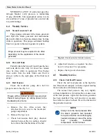
Adjust continuous bleed blowdown valve
opening (See Fig. 6-1.) or auto TDS controls to
maintain desired TDS levels. See Feedwater Man-
ual (R015216), Section 4.1 System Blowdown, for
details.
6.3.5
Walk-Around Inspection
Check for leaks, unusual noise, stack smoke,
and other visual items. Hot lines on manual blow-
down discharge are an indication of valve leakage.
Fig. 6-1.
Check pump belt tension weekly.
Summary of Contents for Steam Master CSMG-15
Page 1: ...STEAM MASTER SERIES USER MANUAL Cover CSMG 15 30 40 R027880B 20190603 ...
Page 8: ...vi The controls and features may differ depending on the unit s size and specifications ...
Page 9: ...vii The controls and features may differ depending on the unit s size and specifications ...
Page 14: ...Specifications_CSM_a fm xii 11 22 2018 This page intentionally left blank ...
Page 44: ...Sect05_CSMG_a fm 5 6 11 26 2018 Steam Master Instruction Manual NOTES ...
Page 68: ...HeatingSect_SM15_a fm A 2 04 30 2019 Fig 01A Main Heating Section SM15 ...
Page 69: ...04 30 2019 A 3 HeatingSect_SM15_a fm FIG 01A Main Heating Section SM15 ...
Page 70: ...HeatingSect_SM15_a fm A 4 04 30 2019 Fig 01B Economizer Stack Outlet Kit SM15 ...
Page 71: ...04 30 2019 A 5 HeatingSect_SM15_a fm FIG 01B Economizer Stack Outlet Kit SM15 ...
Page 72: ...HeatingSect_SM30_b fm A 6 12 05 2018 Fig 01C Main Heating Section SM30 ...
Page 73: ...12 05 2018 A 7 HeatingSect_SM30_b fm FIG 01C Main Heating Section SM30 ...
Page 74: ...HeatingSect_SM30_b fm A 8 12 05 2018 Fig 01D Economizer Coil SM30 ...
Page 75: ...12 05 2018 A 9 HeatingSect_SM30_b fm FIG 01D Economizer Coil SM30 ...
Page 76: ...HeatingSect_SM45_b fm A 10 04 30 2019 Fig 01C Main Heating Section SM40 ...
Page 77: ...04 30 2019 A 11 HeatingSect_SM45_b fm FIG 01C Main Heating Section SM40 ...
Page 78: ...HeatingSect_SM45_b fm A 12 04 30 2019 Fig 01D Economizer Coil SM40 Sht 1 of 2 ...
Page 79: ...04 30 2019 A 13 HeatingSect_SM45_b fm FIG 01D Economizer Coil SM40 ...
Page 86: ...Sep Trap PressMfld_SM153040_b fm A 20 04 30 2019 Fig 02E Pressure Indicating System ...
Page 87: ...04 30 2019 A 21 Sep Trap PressMfld_SM153040_b fm FIG 02E Pressure Indicating System ...
Page 90: ...PumpHkup C1 C2_parts_a fm A 24 03 05 2019 Fig 05A Pump Assy C1 ...
Page 91: ...03 05 2019 A 25 PumpHkup C1 C2_parts_a fm FIG 05A Pump Assy C1 ...
Page 92: ...03 05 2019 A 26 PumpHkup C1 C2_parts_a fm Fig 05B Pump Assy C2 ...
Page 93: ...PumpHkup C1 C2_parts_a fm A 27 03 05 2019 FIG 05B Pump Assy C2 ...
Page 98: ...Blank_Left fm A 32 08 16 2017 This page intentionally left blank ...
Page 106: ...R027906A 2018 10 22 ...
Page 107: ...NOTES ...
Page 108: ...Steam Generator Instruction Manual This page intentionally left blank ...
Page 109: ......


