
T H E C O N T I N U O U S P O W E R C O M P A N Y
Page 27
The unit will start up similarly to normal AC start-up except the AC IN LED will continue to
flash. It will now operate as described above in battery operation.
Loading the System
The system can be loaded up to full rated load. As load is applied, the LOAD METER will
start to turn
ON
. Once full load is achieved, the full LOAD METER should be lit. As additional
load is applied, the top red OVERLOAD LED will come
ON
. If too much overload is applied,
the audible alarm will sound. If this increased load is not removed within five seconds, the unit
will discontinue output operation and latch into an alarm condition. The audible alarm will
continue to sound and the ALARM LED will light. Reducing the load and cycling the System
Power Switch
OFF
then
ON
can reset the system.
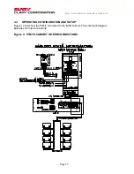
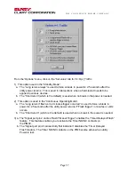
3.6
Optional Communication Procedure
The UPS system includes additional interfaces for communications to host computers or other
similar devices. Their use is optional, but allows for remote monitoring and control of the
power system. Effective utilization of these capabilities will enhance the reliability of the traffic
power system.
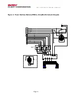
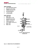
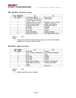
There is one DB-9, subminiature, female connector(Signal) and one RJ45 connector(RS232).
These are provided for communications links to a computer or sophisticated monitoring
device. These two connectors are labeled and used as:
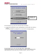
o
SIGNAL provides open collector type contact closures that signal
Utility
Interrupt
,
Low
Battery
and
Timer
conditions to the PIM. These in turn, activate the respective relays
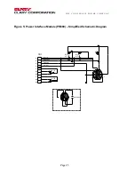
named ‘On-Batt’, ‘Low-Batt’, and ‘Timer’. The SIGNAL port cables to the PIM. The
PIM provides a pass-through port to make these signals available to the user.
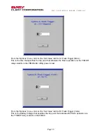
o
RS232 is a true communications signal port. This port connects to standard PC-type
serial ports.


