

T H E C O N T I N U O U S P O W E R C O M P A N Y
Page 15
For 170 type cabinets, upon loss of power the Traffic UPS can actuate the existing Flash Transfer
Relays (FTRs) and Mercury Contactor (MC) to allow the traffic control system to put the cabinet into
Flash Mode operation.
Existing Flasher Modules and Flash Transfer Relays are utilized. The Traffic UPS does not
duplicate or take over flash operation or flash transfer relay functions.
The Traffic UPS is capable of providing continuous, fully regenerated, conditioned, regulated,
sinusoidal (AC) power to selected devices such as signal controllers, counters, modems,
communications hubs, NTCIP adapters, video equipment, etc.
To facilitate emergency crews and police activities, the Traffic UPS is compatible with police panel
functions (i.e. “Signals OFF” switch must kill power to the field wiring even when on UPS/Battery
power).
Utility Voltage Windows and Battery Operation
The UPS operates from utility if the utility voltage is between 85 and 135 vac. When the utility falls
below 85 vac or climbs above 135 vac the UPS operates from the batteries. In the
Standby
modes
of operation, the PIM is activated when the utility is below 100 +/- 2 VAC or above 130 +/-2 VAC.
The UPS does draw from the batteries until the voltage is out of the previously stated limits.
There is a programmable noise rejection window, which specifies how the UPS system treats small
time-duration power glitches. Power disturbances must last at least 40ms to trigger change in
operation. Small disturbances on this order occur frequently due to many different conditions.
These disturbances, however, are not detrimental to traffic controllers. To minimize nuisance
switching this noise rejection window is implemented.
After operating in Standby mode, the UPS monitors the utility voltage. When this voltage is restored
to adequate conditions for 30 seconds, the UPS returns utility power to the cabinet.
Description
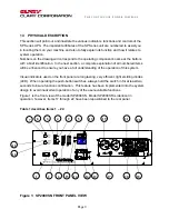
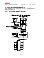
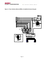
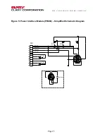
The Traffic UPS consists of three major components, the UPS Power Module, the Power Interface
Module, and the Battery System.
The UPS Power Module consists of the following:
•
True on line, double conversion, pure sine wave, high frequency inverter utilizing IGBT
technology.
•
Local individual indicators for battery status, load levels, battery run-time, and event counter.
•
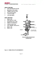
One DB9F connector (Signal) and a RJ45 connector (RS232) for remote signal alarms and true
RS232 monitoring and remote communications.


