


Page 34 of 41
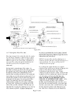
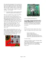
(downstream of the automatic side pressure
regulator), the other is located at the outlet piping of
the heat exchanger. Locate the ¼ turn ball vale on the
automatic (lower) side of the cooling loop, to the left
of the Y strainer. With the engine running from the
main pump controller, SLOWLY rotate the valve
handle clockwise (CW) towards the CAUTION:
CLOSED/NON-AUTOMATIC position to decrease
raw water flow. Continue this until the alarm is
indicated at the controller at interconnect terminal
#311. Upon alarm activation, return ball valve
handle to the NORMAL/OPEN positon. Reset the
main pump controller to re-instate normal operation
of engine and controller.
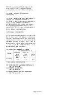
3.5.7 BATTERY REQUIREMENTS
All Clarke engine models require 8D batteries, as
sized per SAE J537 and NFPA20. The battery
should meet the following criteria:
Cold Cranking Amps (CCA @ 0°F): 1400
Reserve Capacity (minutes): 430
Refer to Clarke drawing C131885 (see Page 5)
for additional information on Clarke supplied
batteries.
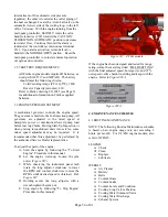
3.6 ENGINE SPEED ADJUSTMENT
A mechanical governor controls the engine speed.
The governor is built into the fuel injection pump. All
governors are adjusted to the rated speed at
nameplate power or maximum allowed pump load
before leaving Clarke. During Start-Up Inspection or
when placing reconditioned units into service, some
minor speed adjustment may be required. It is
recommended that this adjustment be performed by
the authorized Service Dealer representative.
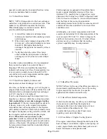
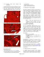
To adjust the speed of the engine:
A.
Start the engine by following the “To Start
Engine” Procedure in this manual.
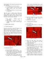
B.
Let the engine warm-up. Loosen the jam
nut(s) (
Figure #37).
C.
While observing the instrument panel tach
rotate the long adjustor clockwise to lower
the RPM and counter clockwise to raise the
RPM’s until desired speed is obtained. Ref.
Figure #37.
D.
Holding secure the long adjustor with a
wrench tighten the jam nut.
E.
Stop engine by following “To Stop Engine”
Procedure in this manual.
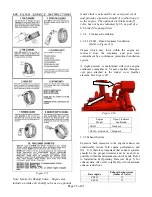
Figure #37 – ZF6H models
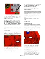
If the engine has been designed and tested for range
rating, stamp the metal tag titled “FIELD SETTING”
with the final adjusted speed, horsepower, and 67%
overspeed verify shutdown setting and keep with the
engine. Refer to
Figure #38A
.
Figure #38A
4.0 MAINTENANCE SCHEDULE
4.1 ROUTINE MAINTENANCE
NOTE: The following Routine Maintenance schedule
is based on an engine usage rate not exceeding 2
hours per month. For UL/FM engine models, also
refer to NFPA25.
LEGEND:
Check
Clean
Replace
o
Lubricate
WEEKLY
Air Cleaner
Battery
Belts
Coolant Hoses
Coolant Leaks
Coolant Levels and Condition
Cooling Loop Valves Position
Cooling Water Solenoid Valve
Cooling Water Discharge
Exhaust System