Page 16 of 41
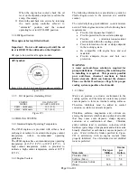
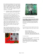
UL/FM Front Opening Instrument Panel
Figure #9
1 – Emergency Operating Instructions
6 – Overspeed Verification
2 – Automatic / Manual Mode Selector
7 – Overspeed Indication Light
3 – Manual Crank Controls
8 – Oil Pressure Gauge
4 – Overspeed Reset
9 – Voltmeters Battery 1 & 2
5 – Manual Mode Warning Light
10 – Coolant Temperature Gauge
IMPORTANT: Main pump controller selector
should be in the
OFF
position when starting from
engine gauge panel. Be sure to return selector on
main pump controller and engine gauge panel to
AUTOMATIC
after completing manual run.
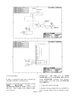
2.5.1.1 Optional Pneumatic Starting System
Some engines may be provided with an optional
pneumatic starting system to crank the engine from a
pressurized receiver tank. See figure 9A for
schematic of the pneumatic starter system and wiring
diagram for field wiring.
5
7
4
1
3
6
8
9
9
10
2


