background image

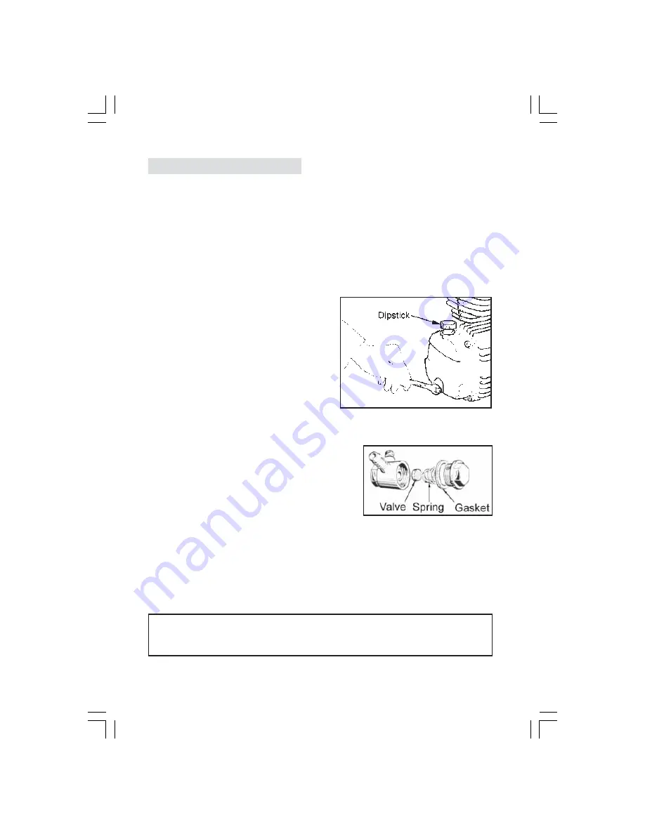
Fig. 6

9

B.

PERIODICALLY

1. After the first 5 hours of running the compressor, check the cylinder head

bolts and motor housing screws and re-tighten if any have worked loose.

2. Every 50 hours (more frequently if used in a dusty environment), clean the air

intake filter, by carefully removing the single screw securing the plastic cover
and withdrawing the sponge element from inside.
Clean the sponge and the inner housing. If necessary, the sponge filter may
be gently washed in warm soapy water, rinsed and allowed to dry thoroughly
before refitting. Ensure that the outer filter cover is then screwed back into its
original position.
If any part of the filter is damaged then  you should obtain a replacement.

3. After the first 100 hours use, replace the

oil completely using Clarke SAE 40
compressor oil. Thereafter, replace the
oil completely after every 500 hours
of operation or every 6 months.

To empty the oil from the machine,
remove the drain plug from the
crankcase cover (see fig. 6).

4. Every 500 hours of operation or every

6 months

clean all the external parts of the

compressor.

(This cleaning makes the cooling
process more efficient and prolongs
the life of the machine).

Check and clean the inlet and outlet
valves

Examine the non-return valve and
replace the gasket if necessary (fig.7)

5. In the event of an air leak follow the procedure below:

Load compressor to maximum pressure

Unplug the compressor

With a brush and soapy water wet all ‘screwed’ air connections

Any leaks will show through the formation of air bubbles.

WARNING

NEVER UNSCREW A CONNECTION WHILST THE AIR RECEIVER IS UNDER PRESSURE.

ALWAYS MAKE CERTAIN THAT THE TANK HAS FIRST BEEN EMPTIED.

Fig. 7

Parts List item No. 59

Summary of Contents for REBEL 30

Page 1: ...OPERATION MAINTENANCE INSTRUCTIONS 0903 REBEL REBEL ...

Page 2: ...tisfactory service GUARANTEE This product is guaranteed against faulty manufacture for a period of 12 months from the date of purchase Please keep your receipt as proof of purchase This guarantee is invalid if the product is found to have been abused or tampered with in any way or not used for the purpose for which it was intended Faulty goods should be returned to their place of purchase no produ...

Page 3: ...al parts can become quite hot during operation Take care not to touch these until the machine has cooled down 9 Always adjust the pressure regulator to the recommended setting for the particular spray gun or tool being used 10 When spraying inflammable materials e g cellulose paint ensure that there is adequate ventilation and keep clear of any possible source of ignition 11 Protect yourself Think...

Page 4: ...WN cord to terminal marked with a letter L or coloured RED Connect BLUE cord to terminal marked with a letter N or coloured BLACK If this appliance is fitted with a plug which is moulded onto the electric cable i e non rewireable please note 1 The plug must be thrown away if it is cut from the electric cable There is a danger of electric shock if it is subsequently inserted into a socket outlet 2 ...

Page 5: ...TION Ref Fig 2 NOTE if you intend using your compressor for spraying read also the Helpful Hints on Spraying booklet supplied with the machine 1 Check that the mains voltage corresponds with that shown on the data sticker on the crankcase cover of the machine 2 Ensure that the ON OFF knob is in the OFF 0 position i e pushed DOWN then plug in and switch on at the mains supply 3 To start the compres...

Page 6: ...etting Read the operating pressure on the outlet pressure gauge NOTE For most spraywork do not exceed 50 psi unless following paint manuf acturer s instructions For other airline equipment such as air tools tyre gauges staple guns paraffin guns etc it may be necessary to set the operating pressure at a higher or lower level IMPORTANT Always refer to the accessory manufacturers recommendations for ...

Page 7: ...r by opening the drain valve 52 NOTE The Rebel 60 incorporates a Regulator Filter which automatically allows any condensate to drain off when pressure in the reservoir is completely relieved Water may also be drained off when the system is under pressure The method of operation is shown in Fig 4 MAINTENANCE A DAILY 1 Check the oil level before you start and top up if necessary useClarke SAE 40 com...

Page 8: ...ce the oil completely using Clarke SAE 40 compressor oil Thereafter replace the oil completely after every 500 hours of operation or every 6 months To empty the oil from the machine remove the drain plug from the crankcase cover see fig 6 4 Every 500 hours of operation or every 6 months clean all the external parts of the compressor This cleaning makes the cooling process more efficient and prolon...

Page 9: ...er NOTE It is also possible that you are using more air than the compressor is capable of delivering Compressor does not start Air receiver charged see also item 1 Open drain cock to expel air Compressor should start again when pressure reduces to approx 95 psi Air leaking from the pressure switch valvewhen the compressor is not running Faulty non return valve First drain the receiver completely o...

Page 10: ...g and many other uses For details contact your local accessory stockist A complete kit is available from your Clarke dealer which is ideal for almost all applications Kit Illustrated KIT1000 Part Number 3110155 Should you experience any difficulties obtaining accessories please contact the Clarke sales department telephone 01992 565300 for details of your nearest dealer 11 Please note that the det...

Page 11: ...13002 62 Washer 1 FN010041000 63 Tube FN046001000 64 Valve 1 FN347027000 No Description Qty Part No REBEL 30 65 Adapter 1 FN199110220 66 Pressure Gauge Res 1 FN330007000 67 Adapter 1 FN011017000 68 Handle 1 FN020121000 69 Output Regulator 1 FN319013000 70 Tap Assy 1 FN322007000 71 Quick Release Conn 1 FN116011065 72 Pressure Gauge Line 1 FN330006000 73 Press Regulator Assy 1 FN321028000 74 Mains l...

Page 12: ...041000 64 Valve 1 FN347027000 65 Adapter 1 FN199110140 66 Pressure Gauge Res 1 FN330007000 67 Adapter 1 FN011017000 68 Pressure Gauge Line 1 FN330006000 69 Tube FN046001000 70 Elbow 1 FN011002000 71 Anti vibration pad 4 FN199575000 72 Pipe 1 FN170GZ0015 73 Adapter 1 FN011248000 74 Screw 4 FN014013042 75 Filter Regulator Assy 1 FN319042000 76 Press Regulator Assy 1 FN321028000 77 Mains lead 1 FN101...

Page 13: ...COMPRESSOR 14 ...

Page 14: ...00026 26 Capacitor 110V 1 FN009200038 27 End Housing Gasket 1 FN116091011 28 Dipstick 1 FN012043000 29 End Housing 1 FN116091002 30 Screw 4 FN014013021 31 Washer 1 FN010072000 32 Screw 1 FN014013024 33 Nut 2 FN014003002 34 Housing 1 FN116091001 35 Circlip 1 FN015005000 36 Shaft Assy 1 FN116091010 37 Bearing 1 FN033027000 38 Slip Ring 1 FN010029000 39 Rotor 1 FN116091020 40 Stator Assy 230V 1 FN416...

Reviews: