30
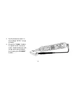
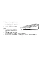
5. Connect the probe tip of the meter and probe tip of the test lead (or test clip) across the power
source or on the two sides of the circuit to be measured.
6. The LCD will display the reading. The polarity of the terminal which the tip of the meter probe
is testing will be displayed.
NOTE:
•
On low voltage range, the meter will have an unsteady reading when test leads are not on the
circuit. This is normal because the meter is very sensitive. When the meter touches the circuit,
the true reading will be displayed.
•
In manual range mode, if only the figure ‘
OL’
is displayed, it indicates a Range Overload
situation and a higher range must be selected.
•
In manual range mode, when the value scale to be measured is unknown beforehand, select
the highest range position and step down gradually.
Summary of Contents for CDM80
Page 1: ...CDM80 PEN PROBE DIGITAL MULTIMETER OPERATING MANUAL Model CDM80 Part No 4500085...
Page 51: ...51 NOTES...
Page 52: ......


