9
3. With assistance if required, rest the upper drum so that it sits on the rim of
the lower drum. Rotate it so that the screws enter the fixing holes from
below. Look to see that the holes for the upper mountings of the mixing
blades also line up with those in the upper drum.
4. When all fixings are correctly lined up, use the screws, nuts and flat
washers to gently pull the upper and lower drum halves together, gripping
the seal between them. Look inside the drum to check that the seal is
sitting correctly in position.
NOTE: It is desirable practice for the screws to be fitted from above,
therefore, remove them one at a time and re-fit the correct way,
adding a spring washer at each position.
5. Finally, tighten all the fastenings progressively.
6. Secure the mixing blades to the upper drum by inserting the dome
headed coachbolt, through the hole in the drum from the outside,
ensuring the square portion of the bolt seats in the square hole in the
drum. The leather washer should bear against the drum.
7. Secure the mixing blade on the inside using a flat washer, spring washer
and nut.
8. Finally, ensure top and bottom mixing blade mountings are tight.
THE MOTOR COVER, MOTOR SUPPORT & DRIVE PULLEY
Note: To restrain it in transit, the
motor will be found bolted
to the inner cover with
suitable packing materials.
Remove the bolts which are
used for this.
1. Bolt the inner motor cover (S) to
the bearing block using two M8 x
25mm bolts with flat washers at
the bolt heads, from within the
inner cover, and spring washers
with nuts to the rear of the
bearing block. Leave the nuts
loose at this stage.
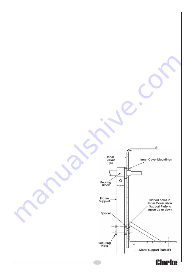
2. Attach the motor support plate
(F), as shown in Fig. 6, by inserting
four M6 x 65mm bolts, through
the holes in the support plate (F),
the slotted holes in the inner
cover (S), and the spacer, which
is inserted between the back of
the inner cover, and the frame
(see fig 6).
Fig. 6
Summary of Contents for CCM125C
Page 13: ...13 COMPONENT PARTS DIAGRAM...
Page 15: ...15 DECLARATION OF CONFORMITY...
Page 16: ......


