background image

12

Parts & Service: 020 8988 7400 / E-mail: [email protected] or [email protected]

TROUBLESHOOTING

If this does not solve the problem, contact the CLARKE Sevice department on 
020 8988 7400.

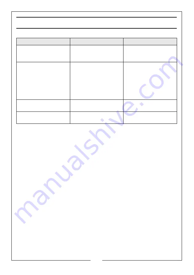
Problem

Probable Cause

Remedy

Pump will not work.

Dirt on valve seat/worn 
seals.

Bleed pump unit or have 
unit overhauled with new 
seals by your dealer.

Pump will not produce 
pressure.
Pump feels hesitant 
under load.

Air-lock.

See “Purging the 
Hydraulic System” on 
page 7. Open the 
release valve and pump 
the handle a couple of 
full strokes. Close the 
release valve. 

Pump feels hesitant 
under load.

Pump cup seal could be 
worn out.

Have the cup seal 
replaced by your dealer.

Piston will not retract
 completely.

Air-lock.

Release air by removing 
the filler plug.

Summary of Contents for 7615203

Page 1: ...WARNING Read these instructions before using the press OPERATION MAINTENANCE INSTRUCTIONS ORIGINAL INSTRUCTIONS GC0820 ISS 1 50 TONNE HYDRAULIC PRESS MODEL NO CSA50FPB PART NO 7615203 ...

Page 2: ...d this manual thoroughly and carefully follow all instructions given In doing so you will ensure the safety of yourself and that of others around you and you can also look forward to the press giving you long and satisfactory service Ensure the press and its components suffered no damage during transit and that all components are present Should any loss or damage become apparent please contact you...

Page 3: ...93 kg Dimensions D x W x H 800 x 1300 x 1960 mm Throat Width 710 mm Throat Depth Ram to pressing plate Platform at highest 0 mm Platform at lowest 950mm No of bed positions 8 140 mm centres Ram travel per stroke 1 72 mm No of strokes to full extension 78 Pressure Gauge type Accuracy class 2 5 Length of Handle 600 mm Oil capacity 1 7 L Oil type VG15 grade hydraulic oil Read instruction manual befor...

Page 4: ...up spills of hydraulic oil immediately as this can be dangerous in a workshop environment 9 Do not let any person who is unfamiliar with hydraulic presses use the press unless they are under direct supervision 10 Keep children and unauthorised personnel away from the work area 11 ALWAYS position the optional safety screen directly front of the workpiece 12 ALWAYS apply the load under the centre of...

Page 5: ... where it will be exposed to the elements as harsh weather conditions will damage the hydraulic parts FITTING THE WINCH During transit the winch is positioned at 180o to its working position inside the frame and must be correctly mounted 1 Turn the winch and bracket around and re fit to the frame with the bolts and washers supplied noting that the handle will be outside the frame for operation FIT...

Page 6: ...acing outwards 3 Fit the key into the slot in the shaft and tap it into place 4 Install the handwheel onto the shaft lining up the slot in the wheel with the retaining key 5 Secure the handwheel with the spring washer flat washer and cross headed screw supplied PROTECTIVE SCREEN OPTIONAL A protective screen CPS50T is available from your CLARKE dealer part no 7615262 1 Bolt the protective screen br...

Page 7: ...HYDRAULIC SYSTEM 1 Open the release valve by turning anti clockwise 2 Pump the handle or foot pedal several full strokes to eliminate any air bubbles from the system 3 Close the release valve turning clockwise POSITIONING THE PRESSING BED 1 Use the winch to raise the pressing bed into a suitable position The arrows on the winch indicate the direction of movement The pressing bed should be as close...

Page 8: ...eam using the adjusting handwheel on the side of the press Always position the ram directly above the workpiece which should be as close to the centre of the press as possible POSITIONING THE PRESSING BED BLOCKS The bed blocks can be placed on the bed with either the flat face or the V supports facing upwards They are prevented from slipping out of position by the retaining pins which drop down wi...

Page 9: ...n angle 2 Close the release valve by turning clockwise until tightly closed 3 Select either SLOW SPEED or FAST SPEED using the knob on the side of the pump cover Fast speed allows faster movement but greater effort will be required 4 Pump the handle or foot pedal to bring the ram very lightly into contact with the workpiece 5 Manoeuvre the workpiece or slide the ram to one side so that the desired...

Page 10: ...ain completely in line with no risk of slipping 9 Observe the reading on the pressure gauge and take care not to exceed the rated working pressure of the press The scale from 50 metric tonnes upward is highlighted in red indicating pressure is being applied above the rated maximum working pressure 10 When the pressing task is complete turn the release valve control knob anticlockwise in small incr...

Page 11: ... are tight and inspect for cracked welds bent loose or missing parts Clean any foreign material from the ram carrier Keep the protective screen if fitted clean at all times Check the hydraulic connections for leaks Replace or properly repair any damaged or leaking hydraulic components before using Note any loss of oil and if oil is seen to become foul replace using CLARKE hydraulic oil Part No 305...

Page 12: ... worn seals Bleed pump unit or have unit overhauled with new seals by your dealer Pump will not produce pressure Pump feels hesitant under load Air lock See Purging the Hydraulic System on page 7 Open the release valve and pump the handle a couple of full strokes Close the release valve Pump feels hesitant under load Pump cup seal could be worn out Have the cup seal replaced by your dealer Piston ...

Page 13: ...AGRAM NO DESCRIPTION NO DESCRIPTION 1 Elbow connector 12 Ring 2 Ram cylinder 13 Ring 3 Pin 14 O ring 60 5x2 5 4 Nut 15 Piston 5 Spring 16 Grub screw 6 Grub screw 17 Washer 7 Nut 18 Bolt M10 x80 8 Y ring 19 Ram Toe 9 Back ring 20 O ring 120x5 3 10 Piston head 21 Mounting Collar 11 O ring 90 5 x 5 3 22 O ring 74 5x5 3 ...

Page 14: ...er 45 Straight connector 13 Pivot bolt 46 Long roller 14 Bolt M10 x 25 47 Roller 15 Winch assembly 48 Circlip 20 16 Bolt 49 Pressing block set 17 Winch support bracket 50 Pressing beam 18 Washer 10 51 Butterfly clip 19 Spring Washer 10 52 Pressing beam support pin 20 Nut M10 53 Hydraulic pump assembly 21 Bolt M12 x 30 54 Frame upright 22 Bolt M12 x 35 55 Pedal footpad 23 Support beam 56 Screw 24 S...

Page 15: ...15 Parts Service 020 8988 7400 E mail Parts clarkeinternational com or Service clarkeinternational com FRAME ASSEMBLY PARTS DIAGRAM ...

Page 16: ...Bush 13 High pressure washer 44 Lock nut M6 14 High pressure oil spring 45 Hoop 15 Steel ball 13 5mm 46 Shaft M10x80 16 Low pressure oil sucking spring 47 Flat washer 6mm 17 Steel ball 9 5mm 48 Spring washer 18 Pump core 49 Inner hex bolt M6 x 16 19 Star O ring 50 Oil reservoir 20 Pump core back ring 51 Reformed bolt 21 Pump core O ring 52 Flat washer 14 22 Pump core sleeve 53 Spring washer 14 23 ...

Page 17: ...17 Parts Service 020 8988 7400 E mail Parts clarkeinternational com or Service clarkeinternational com PUMP PARTS DIAGRAM ...

Page 18: ...18 Parts Service 020 8988 7400 E mail Parts clarkeinternational com or Service clarkeinternational com DECLARATION OF CONFORMITY ...

Page 19: ...om the date of purchase Please keep your receipt which will be required as proof of purchase This guarantee is invalid if the product is found to have been abused or tampered with in any way or not used for its intended purpose Faulty goods should be returned to their place of purchase no product can be returned to us without prior permission This guarantee does not effect your statutory rights ...

Page 20: ......

Reviews: