21
2. Models 151TE and 160EN
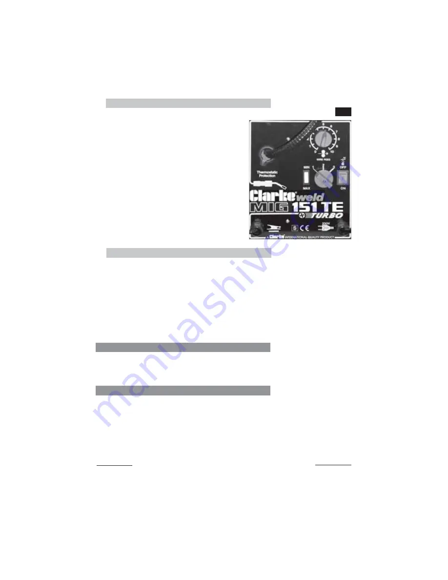
These models are provided with an ON/
OFF switch, a rotary knob, with
graduations marked from 0 to 10, a single
two position switch marked Max - Min,
and a 3-position rotary switch as shown
in Fig.9.
The 10-position rotary switch is used to
control wire speed, and the other two
switches are used to control the welding
current according to the type and
thickness of material to be welded, and
in accordance with the charts shown in
the ‘Reference Tables’ on pages 24 and
25. Set the controls accordingly.
Fig.9
D. Trim the Welding Wire
Trim the welding wire so that it protrudes no more than 5mm from the end of the
shroud.
E. Attach the Earth Lead
Attach the earth lead to the workpiece with the earth clamp, as close to the
point of weld as possible, without it being intrusive.
Ensure there is good contact, if necessary, clean the area with a wire brush
beforehand.
Your welder is now fully prepared for welding.
3. ALL Models
The 10-position wire speed control should be set to 6 to begin with for welding steel,
and 9 for welding aluminium, then adjusted as required.
Note: This control is for fine tuning the wire speed. The speed of wire delivery will increase
automatically as the current is increased and vice versa. Therefore, once the ideal speed
is achieved, by fine tuning,it should not be necessary to adjust this control when the
welding current is changed.
It is always better to start with too high a speed, and back off slightly, to avoid the possibility
of the wire welding itself to the tip.
Summary of Contents for 6014530
Page 27: ...27 WIRING DIAGRAMS MIG 110E MIG 110EN...
Page 28: ...WIRING DIAGRAMS MIG 130EN MIG 135TE 28...
Page 29: ...WIRING DIAGRAMS MIG 151TE MIG 160EN 29...
Page 31: ...PARTS DIAGRAM MIG 110E 31...
Page 33: ...PARTS DIAGRAM MIG 110EN 33...
Page 35: ...PARTS DIAGRAM MIG 130EN 35...
Page 37: ...PARTS DIAGRAM MIG 135TE 37...
Page 39: ...PARTS DIAGRAM MIG 151TE 39...
Page 41: ...PARTS DIAGRAM MIG 160EN 41...


