


CJ-981E
61
3
CJ-981E
4
CJ-981E
Note:
Be sure to unfold this page and refer to the front diagrams as you read each chapter.
Remarque:
Veuillez déplier cette page et vous référer aux schémas quand vous lisez chaque chapitre.
Hinweis:
Bitte diese Seite ausfalten und beim Lesen der einzelnen Kapitel die Frontdiagramme beachten.
Nota:
Assicurarsi di aprire questa pagina e fare riferimento a questi diagrammi quando si legge ciascun capitolo.
2. NAMES AND FUNCTIONS OF PARTS
2. NOM ET FONCTIONS DES ORGANES
2. BEZEICHNUNG UND FUNKTION DER TEILE
2. NOME E FUNZIONE DELLE VARIE PARTI
English
Fran
ç
ais
Deutsch
Italiano
English
ADJ
POWER
SELECT
IRIS
ZOOM
CAM1/DIM
FUNC
MODE
[FUNC]
[MODE]
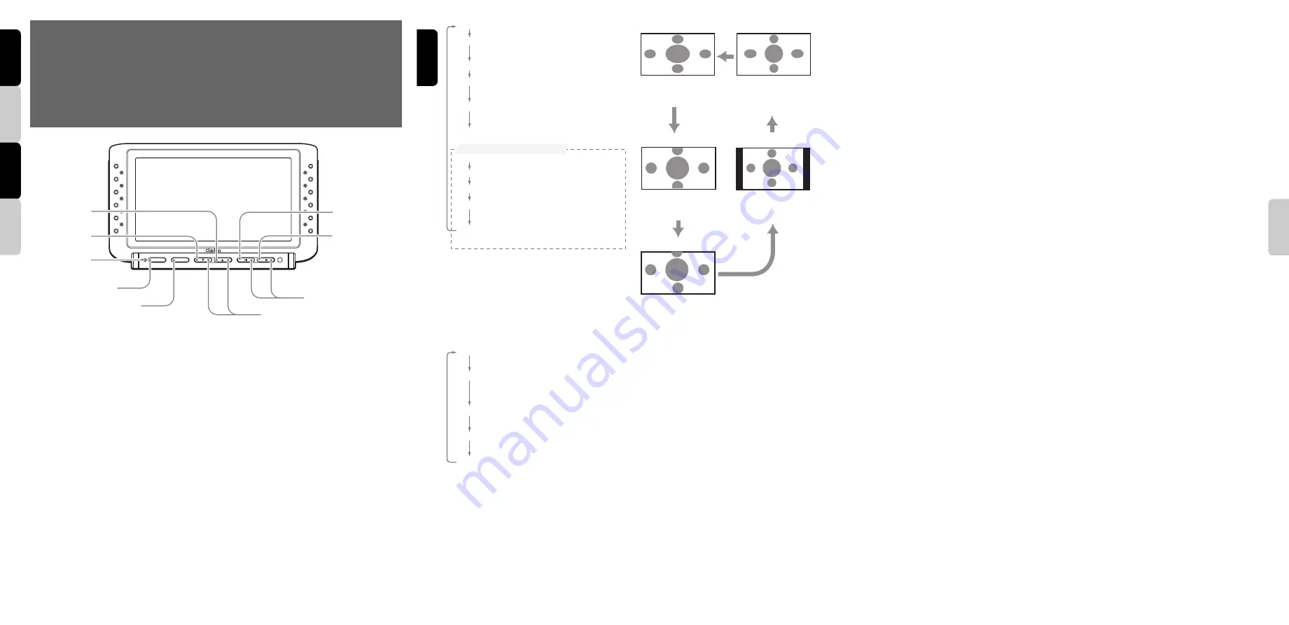
[
z
], [
w
]
[
Å
], [
Î
]
[CAM1/DIM]
[ZOOM]
[IRIS]
[SELECT]
[
POWER
]
[IRIS] button
• During the “
CAM
” mode, pressing this button
causes the camera to alterate between
backlight compensation ON and OFF.
[SELECT] button
• During the “
CAM
” mode, pressing this button
causes the screen mode to change in the
following order: CAMERA1
➜
CAMERA2
➜
CAMERA3
➜
CAMERA1
[POWER] indicator
• Light turns off when the power is turned ON,
and illuminates when power is turned OFF.
When unit is turned OFF, it enters the standby
mode, and if the vehicle’s transmission is
shifted to reverse gear, the monitor
automatically powers on and displays the
rear-view camera image.
[FUNC] button
• When power is OFF, pressing this button will
turn power ON.
• When power is ON, pressing this button will
switch unit alternately between “
CAM
”, “
VTR
”,
and “
RGB
” modes. If the button is held
depressed for about 1 second, power is
turned OFF.
[MODE] button
• In “
CAM
” mode, pressing this button causes
the setting menu screen to change (screen
size is fixed at “
F-WIDE
” (full wide)).
Italiano
CAM:
displays image from camera
MARKER:
displays setting menu for scale
markers
CAM TYPE:
displays camera type setting menu
MARKER SELECT:
displays marker pattern
setting menu
MARKER ADJUST:
displays marker display
position setting menu
TIMER:
displays timer operation menu
<Camera switching settings>
CAM1 AUTO:
CAMERA1 image linked setting
CAM2 AUTO:
CAMERA2 image linked setting
CAM3 AUTO:
CAMERA3 image linked setting
CAM2 HAZARD:
CAMERA2 hazard linked setting
CAM3 HAZARD:
CAMERA3 hazard linked setting
∗
During display of images from
CAMERA
2 or
CAMERA
3, the “
MARKER
”, “
MARKER
SELECT
”, and “
MARKER ADJUST
”
setting menus do not appear.
[MODE] button
• During “
VTR
” mode, pressing this button
causes the screen to change in the following
order:
F-WIDE:
4:3 ratio images are stretched
horizontally to fill the entire screen.
CINEMA 1:
4:3 ratio images are displayed
“letterbox” style, with black band at top
and bottom.
CINEMA 2:
Use this mode if subtitles are cut off
when using “
CINEMA 1
”.
NORMAL:
Normal 4:3 ratio television display
mode.
WIDE:
4:3 ratio images are stretched
horizontally on left and right sides only.
Note:
• Images displayed in “
VTR
” mode are those input
through the power supply box’s video input
connectors. In order to prevent distractions to the
driver, these images cannot be viewed unless the
vehicle is stopped and the parking brake applied.
■
When normal 4:3 ratio images are input,
the image shape will differ depending on
the display mode setting, as follows:
°
WIDE mode
Left and right
sides of image are
stretched
horizontally.
°
CINEMA 1 mode
Top and bottom
portions of image
are cut off.
°
F-WIDE mode
Entire image is
stretched
horizontally.
°
NORMAL mode
Right and left
edges of screen
appear as black
stripes.
°
CINEMA 2 mode
Top portion of
image is cut off.
°
Regarding WIDE screen images
Wide television monitors are equipped with
controls allowing the user to select from a
variety of display modes. If the mode chosen
differs from the ratio of the original television
program or movie software, the screen image
will appear distorted from its original
appearance. This point should be taken into
account when selecting a video mode.
[
z
], [
w
] buttons
• In the setting menu, use to move to different
menu selections or change adjustment levels.
[
Å
], [
Î
] buttons
• In the setting menu, use to change
adjustment levels.
[CAM1/DIM] button
• Switches to image from CAMERA1 input.
• When showing normal image, holding the
button depressed for about 1 second
switches dimmer between Light/Dark settings.
[ZOOM] button
• During the “
CAM
” mode, pressing this button
causes the camera to alternate between
camera zoom ON and OFF.
Summary of Contents for CJ-981E
Page 14: ...16 CJ 981E English...


