Clarion CJ-981E Owner'S Manual & Installation Manual Download Page 11

CJ-981E

13

English

5. INSTALLATION

Before Installing

WARNING

• Always disconnect the negative 

-

-

-

-

-

terminal cable from the vehicle battery
before performing any installation work.

If the battery is not disconnected, a short-
circuit could occur during installation due to
accidental contact between 

+

 and 

-

 wires,

causing vehicular damage or personal injury.

• Do not install in any location that may

impede the operation of air bags.

Installing the monitor or wiring in any location
that impedes the free operation of airbags
may result in improper operation in the event
of a vehicle accident, resulting in personal
injury.

• Do not install in any location that impedes

forward vision of the driver, that interferes
with vehicle operation, or that presents a
safety danger to passengers of the vehicle.

Installing the monitor in such locations could
result in dangerous accidents or injuries.

Installing the Monitor Stand/
Display Unit

Note:

• Clean away all dust and dirt from the installation

surface before installing.

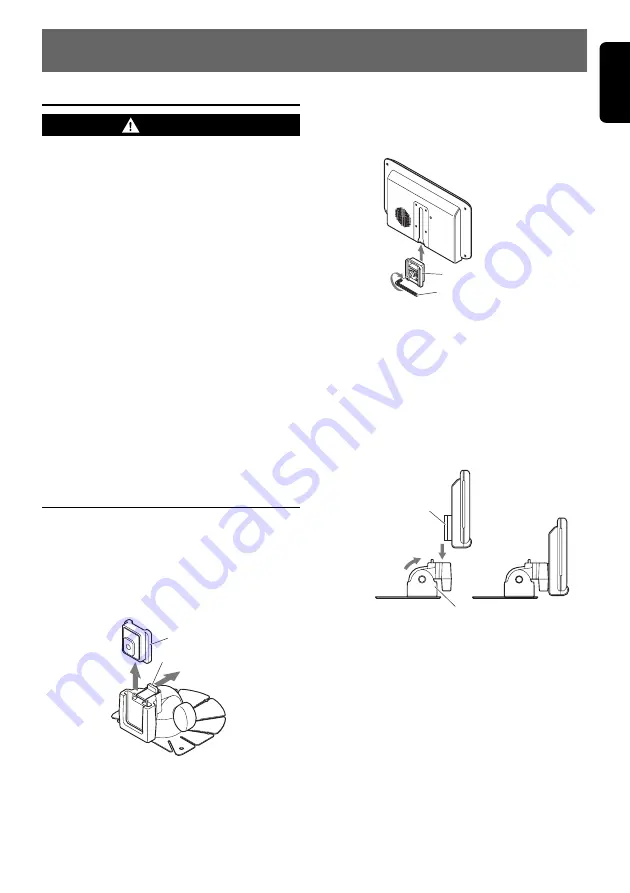
1. Lift up the guide holder while pressing down

on the unlock knob to remove the guide
holder.

Guide holder

Unlock knob

2. Slide the guide holder into the groove

provided in the back of the display unit.

Tighten the screw on the guide holder using
the Allen key provided with the display unit.

Guide holder

Allen key (provided)

3. Install the display unit on the monitor stand,

and determine its attachment position.

Insert the guide holder into the monitor stand
until you hear it click into place.

Determine the attachment position after
adjusting the angle.

Note:

• Do not remove the peel-off sheet from the base of

stand base.

Guide holder

Adjust the angle 
of the stand.

Stand base

4. Align the stand base with the profile of the

attachment surface and bend the stand
base.

Notes:

• Bend the stand base so that it contact-fits the

profile of the attachment surface. Gaps in the
attachment may cause the stand base to come
away from the attachment surface.

• Do not remove the peel-off sheet from the base of

stand base.

Summary of Contents for CJ-981E

Page 1: ...safety scale marks displayed onscreen assist the driver in determining distances to obstacles Backlight compensation function The camera s aperture iris can be adjusted to provide brighter viewing und...

Page 2: ...e linked setting CAM3 AUTO CAMERA3 image linked setting CAM2 HAZARD CAMERA2 hazard linked setting CAM3 HAZARD CAMERA3 hazard linked setting During display of images from CAMERA2 or CAMERA3 the MARKER...

Page 3: ...h hard objects Do not leave the LCD panel while it is wet since discoloration or stains may occur or moisture may invade the interior of the unit resulting in damage In the event water drops are splas...

Page 4: ...benzene thinner or other volatile chemical cleaners to clean the screen This equipment has been tested and found to comply with the limits for a Class B digital device pursuant to Part 15 of the FCC R...

Page 5: ...mode screen Setting Item BRIGHT luminance HUE color tone COLOR saturation DIMMER screen brightness Darker Redder Less Darker Lighter Greener More Lighter When in the VTR mode the screen will change to...

Page 6: ...switch to CAM mode 2 Use the SELECT z button to select the CAMERA1 image 3 Press the MODE button to switch to the MARKER menu Each time the MODE button is pressed the mode cycles through the modes in...

Page 7: ...s in the following order CAM MARKER MARKER ADJUST CAM 4 Press the z and w buttons as required to adjust the scale marker position up down The marker display position can be moved 10 steps above V 1 to...

Page 8: ...reset and restarts from the newly reset time Setting the Camera Linked Image Switch CAM AUTO CAM HAZARD Automatic linked display This setting is used to select whether the camera image is automatical...

Page 9: ...the CCD Camera s Image ZOOM Function This function operates only when a zoom equipped CCD camera is connected and when the CAM TYPE setting has been used to select a zoom equipped camera 1 Press the Z...

Page 10: ...rn to the ordinary dimmed screen the indicator DIM will once again appear at the top of the screen 3 To dim the screen when the parking lamps are OFF hold the CAM1 DIM button depressed for about 1 sec...

Page 11: ...d Display Unit Note Clean away all dust and dirt from the installation surface before installing 1 Lift up the guide holder while pressing down on the unlock knob to remove the guide holder Guide hold...

Page 12: ...ttachment surface cannot be obtained by the double sided adhesive tape alone depending on the material of the attachment surface or heat For extra safety firmly fasten the stand base in place using th...

Page 13: ...icator appears on the screen hold the CAM1 DIM button depressed for about 1 second to set dimmer to OFF This may occur when internal vehicle temperatures are below 0 C or above 60 C Adjust vehicle pas...

Page 14: ...16 CJ 981E English...

Page 15: ...safety scale marks displayed onscreen assist the driver in determining distances to obstacles Backlight compensation function The camera s aperture iris can be adjusted to provide brighter viewing und...

Reviews: