


20
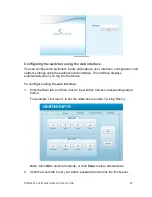
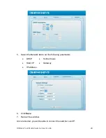
HDBaseT 4x4 Matrix Switcher User Guide
Status.
Returns the current status of the input channel to the
output channels one by one.
Save[X].
Saves the present operation to the preset command [X],
ranges from 0 to 9.
Recall[Y].
Recalls the preset command [Y].
Clear[Y].
Clears the preset command [Y].
PWON.
Work in normal mode.
PWOFF.
Enter into standby mode.
/%[Y]/[X]:[Z].
HDCP management command. [Y] is for input (value: I) or
output (value: O). [X] is the number of one port, if the
value of X is ALL, it means all ports. [Z] is for working
status (value: 1 or 0).
Y=I and Z=1, means the input port is compliant with
HDCP.
Y=O and Z=1, means output with HDCP.
Y=I and Z=0, means the input port is not compliant with
HDCP.
Y=O and Z=0, means output without HDCP.
%0801.
Automatic HDCP management.
%0800.
Manual HDCP management.
[x1] R[x2].
Transfer the IR signal from the input channel [x1] to the
output channel [x2].
/+[Y]/[X]:******.
Set communication between PC and HDBaseT Receiver.
Y is for port.
Y = 1, 2, 3 or 4, means to send the command in a given
baud rate to the corresponding HDBaseT Receiver.
Y = 5, means to send the command to all connected
HDBaseT receivers.
Y = A, B, C or D, means to send the command to the
corresponding HDBaseT receiver only when in normal
mode.
Y = E, F, G or H, means to send the command to the
corresponding HDBaseT receiver only when in standby
mode.
X is for baud rate. Value ranges from 1 to 7.
1 = 2400, 2 = 4800, 3 = 9600, 4 = 19200, 5 = 38400,
6 = 57600, and 7 =115200)
***** is for the data (max 48 Byte)
The symbol “.” is the end of one command. If there are
some symbols with “.” in one command, then this case is
allowed and the last one is the end of this command.
%9900.
Set as infrared carrier following mode.
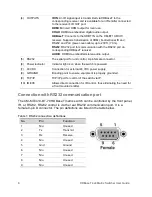
Summary of Contents for CM-MT4410-BT-70
Page 1: ...2014 12 352 Rev 03 HDBaseT 4x4 Matrix Switcher Model CM MT4410 BT 70...
Page 2: ......
Page 4: ......
Page 8: ......
Page 11: ...HDBaseT 4x4 Matrix Switcher User Guide 3...
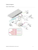
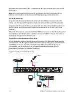
Page 17: ...HDBaseT 4x4 Matrix Switcher User Guide 9 System diagram Figure 3 System diagram...
Page 44: ......


