29
Continued On Next Page
☛
☛
☛
☛
☛
❑
Plug one 12" servo extension onto each of the aileron servo leads.
❑
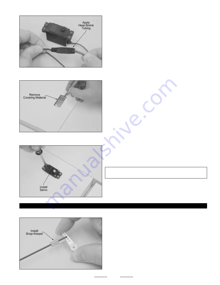
To prevent the servo leads from pulling apart during assembly,
or worse, during flight, secure the plugs together, using a short piece of
3/8" diameter heat-shrink tubing.
❑
Using a modeling knife, cut away and remove the covering material from over the two precut aileron servo lead exit holes in the
bottom of the wing. The holes are located 7/8" out from the centerline of the wing and 7" behind the leading edge.
❑
Install your aileron servo into the servo tray, making sure to first drill
1/16" diameter pilot holes for the mounting screws.
✦
✦
✦
✦
✦
IMPORTANT
✦
✦
✦
✦
✦
The servo output shaft should be toward the trailing
edge of the wing, as shown.
❑
Repeat the previous procedures to install the second aileron servo
into the other wing tip panel.
STEP 2: INSTALLING THE AILERON PUSHRODS
❑
Using a modeling knife, cut away all but one arm from a "4-point" servo horn.
❑
Enlarge the hole in the servo arm that is 9/16" out from the center of
the servo arm, using a 5/64" diameter drill bit.
❑
Install the 90º bend in one 3-1/2" long threaded pushrod wire into
the hole that you just enlarged, using the nylon snap-keeper provided.
When installing the snap-keeper, make sure that it "snaps" firmly into
place over the pushrod wire.
☞
The pushrod wire should be orientated on top of the servo arm,
as shown.
❑
Using a modeling knife, carefully cut away and remove the covering
material from over the two aileron servo trays in the bottom of the wing.
One servo tray is located in each wing tip panel, 4-1/4" in front of the
aileron hinge line and 1-3/4" out from the wing tip panel glue joint.
❑
Working with one aileron servo for now, run the servo extension lead through the wing from within the servo tray and out the
servo lead exit hole, using the length of string that's been preinstalled through the wing.


