


28
ISA-E5 User`s Manual
CPU FAN Power Connector
This is a 3-pin header for the CPU fan.
3 2 1
Pin #
Signal Name
1
Ground
2
FANPWR1
3
VCC
System FAN Power Connector
This is a 3-pin header for the System fan.
3 2 1
Pin #
Signal Name
1
Ground
2
FANPWR2
3
VCC
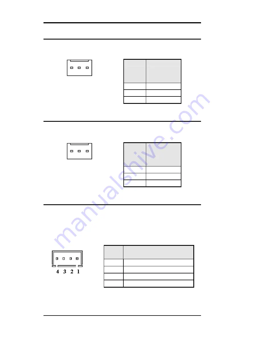
ATX Power Connector
This is a four-pin connector to support the ATX power and
corresponding back-plane. When your back-plane is configured to
perform ATX power supply Soft-on/off function, you have to connect
the control signals and stand-by power on this connector to your
back-plane by a corresponding cable.
Pin #
Signal Name
1 PWR_GD
2
5V_SB (s5V)
3 PS-ON
(soft
on/off)
ATX-PWR
4 GND
Summary of Contents for CJ ISA-E5
Page 10: ...2 ISA E5 User s Manual Chapter 1 Features Specifications Features 3 Specifications 4...
Page 15: ...ISA E5 User s Manual 7 Dimensions 185mm W x 127mm L 4 screw holes on four corners...
Page 16: ...8 ISA E5 User s Manual This page is intentionally left blank...
Page 19: ...ISA E5 User s Manual 11 Jumper Locations on the ISA E5...
Page 24: ...16 ISA E5 User s Manual Connector Locations on the ISA E5...