


ISA-E5 User`s Manual
17
Front Panel Connector
The front panel of the case has a control panel, which provides light
indication of the computer activities and switches to change the
computer status.
PWR HDD PWR Reset
BTN LED LED
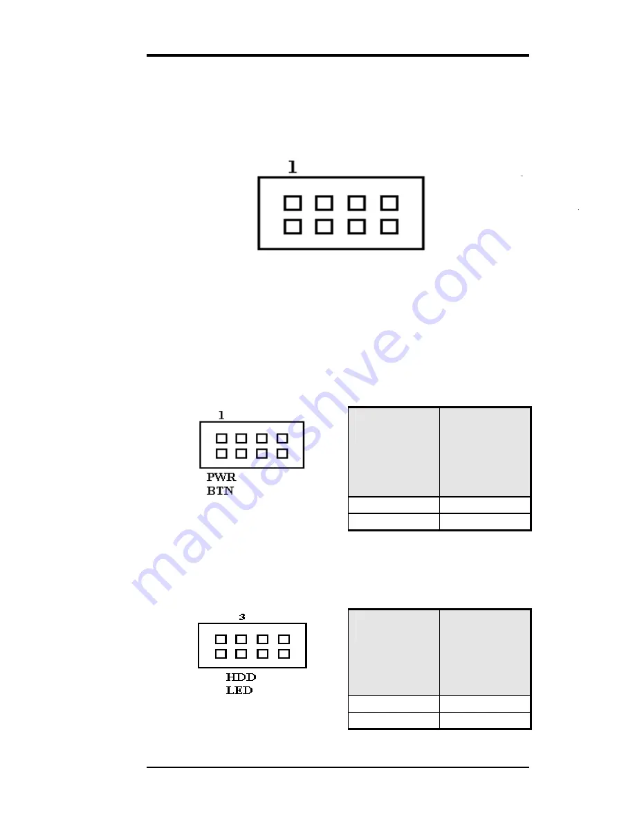
ATX Power ON/OFF Button
This 2-pins connector acts as the “Power Supply On/Off Switch”
on the ISA-E5 single board computer card. When pressed, the
switch will force the single board computer card to power on.
When pressed again, it will force the single board computer card
to power off.
PWR BTN
Pin #
Signal Name
1
5VSB
2
PWRBTN
IDE Hard Disk LED Connector
This connector connects to the hard drive activity LED on control
panel. This LED will flash when the HDD is being accessed.
IDE LED
Pin #
Signal Name
3
VCC
4
HDDLED
Summary of Contents for CJ ISA-E5
Page 10: ...2 ISA E5 User s Manual Chapter 1 Features Specifications Features 3 Specifications 4...
Page 15: ...ISA E5 User s Manual 7 Dimensions 185mm W x 127mm L 4 screw holes on four corners...
Page 16: ...8 ISA E5 User s Manual This page is intentionally left blank...
Page 19: ...ISA E5 User s Manual 11 Jumper Locations on the ISA E5...
Page 24: ...16 ISA E5 User s Manual Connector Locations on the ISA E5...